Documentation Library
Qubic System — product manuals and technical documentation.
76 manuals
·
6 categories
Software
Software applications and simulation guides
Hardware
Motion platform hardware manuals
Tutorials
Step-by-step guides and tutorials
Product Cards
Product specification sheets and datasheets
Miscellaneous
Wallpapers and additional resources
3D Prints
3D printable models for motion platforms


QS-220 R2 and older
Use this user manual if you have second revision (R2) of the system or older model
1 Important Safety Instructions
Info
Read all safety instructions before installing and using this product. Save this document for future reference. If ownership of this product is transferred, be sure to include this manual.
Warning
QS-220-PL is not intended for use by children under 16 years of age. Close supervision and safety instruction is required when this product is used by or near children or people with reduced physical, sensory or mental capabilities. Keep the packaging away from small children as it poses a suffocation risk.
1.1 Essential Information
To reduce the risk of burns, fire, electrical shock, injury or mechanical damage:
- Use the QS-220-PL only for its intended purpose, according to instructions.
Danger
Warning: Always turn all the power switches off before plugging and unplugging the QS-220-PL. Dangerous voltages level can be present in Power Cabinet for a few minutes after turning off the machine.
- Unplug the QS-220-PL from the power source if it is not used for an extended period or when there is a need to perform hardware installation, maintenance, servicing or repairs.
- Turn the QS-220-PL off when it is not in use.
- The QS-220-PL was designed for indoor use only - Do not store or use the product outdoors.
- Keep the QS-220-PL away from the heat sources, high humidity, water, and other liquids. Do not store in cold place where condensation may occur.
- Do not disassemble the product. Any tampering with or altering the product will void the warranty, poses a serious risk of electric shock, and may irreparably damage the product.
- Do not cover the vents.
- Keep the power cord plug and the socket dry, clean and dust-free.
- Protect the power cord from damage caused by being stepped on, rubbed against, or pinched.
- Do not use the QS-220-PL if the ambient temperature is below 4° Celsius (39° Fahrenheit) or above 45° Celsius (113° Fahrenheit).
- Do not use the QS-220-PL if it has been damaged, or any component is broken or missing. Please contact technical support.
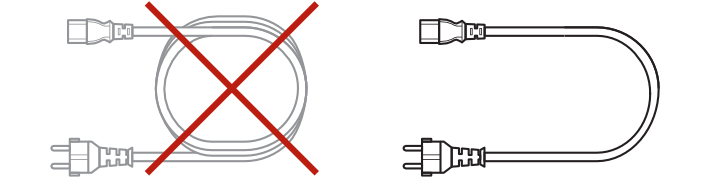
- Do not use attachments or replacement parts not recommended or approved by the manufacturer. Do not replace the power cables provided with the product. Use certified power and USB cables only.
- Connect the QS-220-PL to a properly grounded outlet only. See grounding instructions in section 2.5.
- If you want to increase safety level of the system, you can add external safety devices. For detailed information check section 6.
Warning
Stop using the QS-220-PL immediately and contact technical support when the machine starts to emit unusual noise, smoke or any other suspicious behaviour indicating the machine is not working properly.
Info
The maximum supported length of cables is 3 meters:
- the maximum supported length of the USB cable is 3 meters
- the maximum supported length of the M-BUS cable between M10 and QS-SB2 is 3 meters
- the maximum supported length of the M-BUS cable between the QS-SB2 is 3 meters
- the maximum supported length of the MotionLock cable is 3 meters
1.2 Health and Safety Instruction
The safety of Qubic System users is the top priority. To protect users and bystanders against injuries caused by mechanical parts movement and electrical connectivity, the following instructions must be strictly performed.Warning
As with any mechanical device, the user is responsible for inspecting the condition of the machine prior to use and adhering to safe operating procedures.
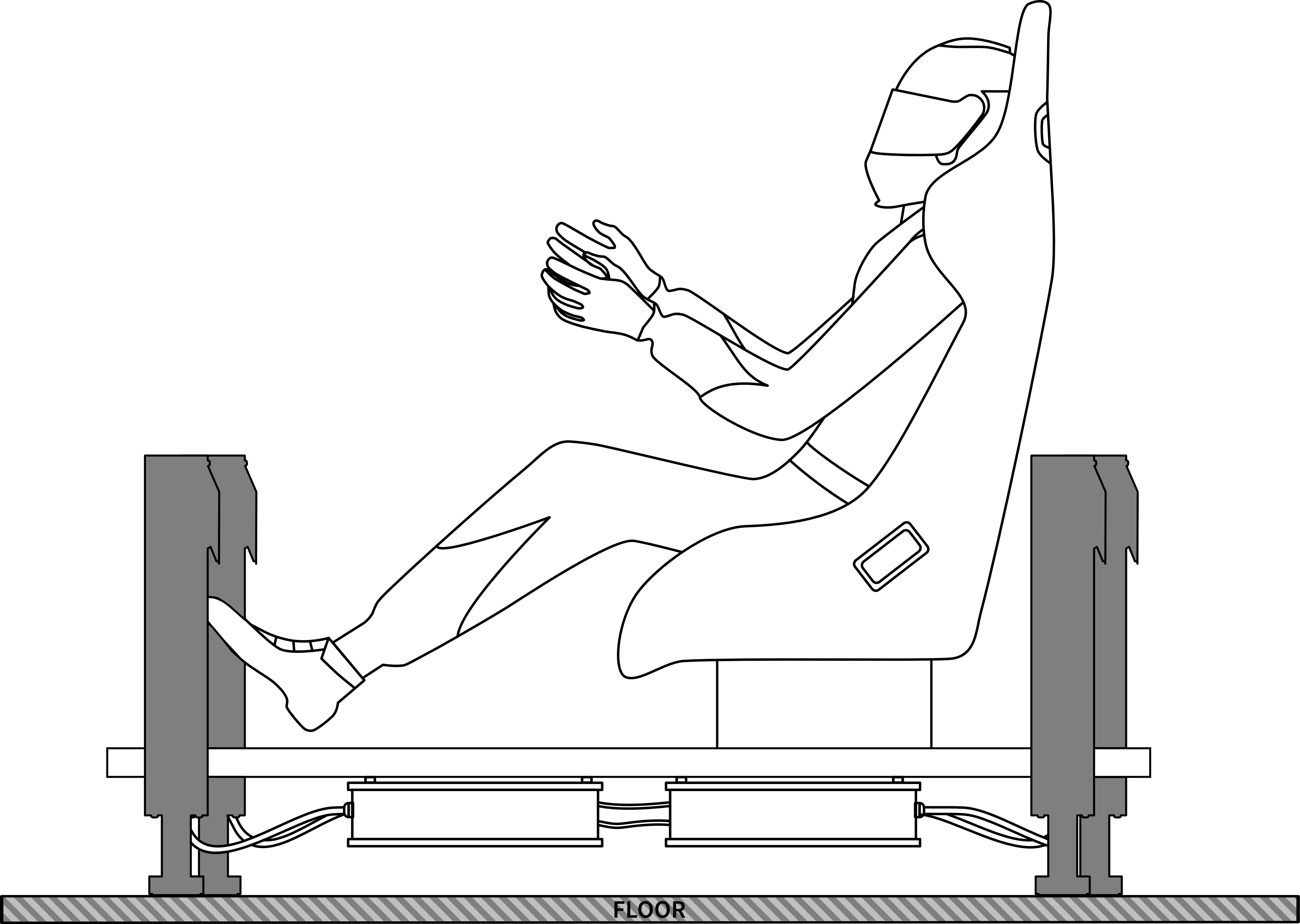
- Check if nothing is blocking machine movements or air vents. The minimum distance between the air vents in the power cabinets and any outside parts of the cockpit equipment is 10 cm or 4 in.

- Check if cables are mounted properly – they are not stretched or loosely connected to the socket and placed out of the moving range of the system components.
- Check that all elements are properly fixed.
- Check if there are no sharp edges nearby.
Danger
Warning: Dangerous voltage level may occur in Power Cabinet and cables during the operation and for a few minutes after turning off the machine.
- Check if everyone around is aware of machine rapid movements.
- Make sure that no one stands in the range of motion (minimum 1.5 m).
- Kids should be kept away from the machine.
- Pets should be kept away from the machine.
- When the QS-220-PL is turned on, it performs start-up calibration.
Warning
QS-220-PL will move automatically after turning it on in order to perform start up procedure. Please be away of that movement and do not try to interrupt it.
- Do not interrupt or change the weight of payload mounted to the QS-220-PL during start-up calibration.
- Motion Lock Switch should be mounted close to the operator of the machine – it has to be easily reachable in every situation.
- Check Motion Lock Switch AT LEAST once a month to reduce the possibility of unknown failure – more information available in chapter 4.
- Before getting on or off the machine, make sure to push the Motion Lock Switch.
- In case of game crash, the Motion Lock Switch must be pressed before getting off the machine.
Warning
Motion Lock and Park Mode option does not guarantee safety. For more details see section 6.
- For VR Headset users:
- Remove the VR goggles before entering or exiting the rig.
- Check very carefully if cables from VR Headset are not limiting the operation range of QS-220-PL.
- Check if the whole VR setup is not in range of motion of the machine.
- Check if cables are protected from being crushed by the QS-220-PL – Do not place them loosely under the motion rig.
Info
Check if connected PC is capable of running the game at stable 90 frames per second or more when VR Headset is used. Lower values can cause VR sickness.
- Do not use QS-220-PL if you are pregnant, tired, or under the influence of alcohol or drugs.
- STOP USING the QS-220-PL immediately if pain, fatigue or any discomfort appears.
- For every two hours of playing, we recommend at least 15 MINUTES OF BREAK.
- Do not put your hands or legs in the actuators range of motion!
- Do not use the QS-220-PL around small children or pets.
- Do not put any items between actuators and stabilization plates.
- Do not pull the wires connecting the actuators with the power cabinets.

2 Product description
QS-220-PL is designed with upgradability in mind – it is possible to expand 2DOF Setup later on. Available variants are presented below.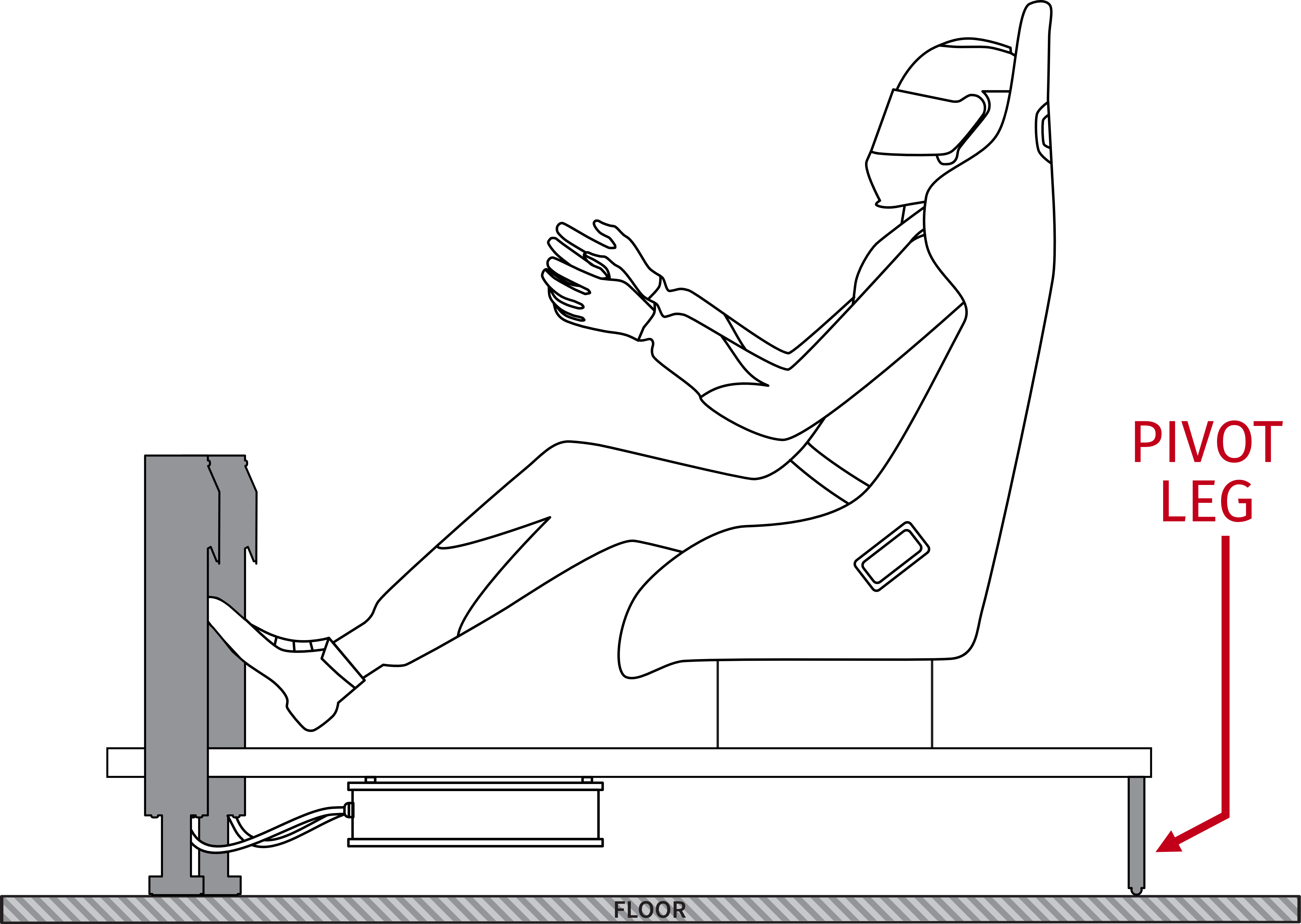
Warning
QS-220-PL is delivered without the pivot leg.
2.1 Intro Set
Warning
Check if the package contains all listed parts. If it is incomplete, please contact the distributor/reseller.
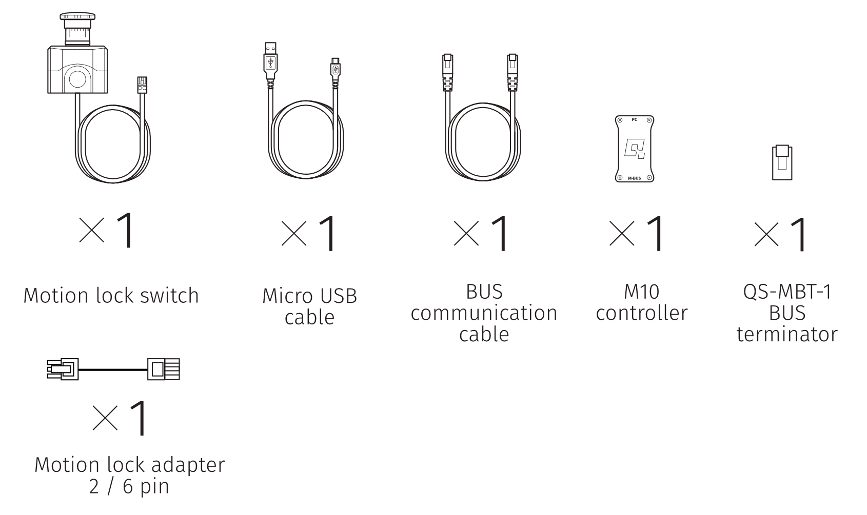
- Motion lock switch (x 1) Micro USB cable (x 1) BUS communication cable (x 1)
- M10 controller (x 1) QS-MBT-1 BUS terminator (x 1) Motion lock adapter (x 1)
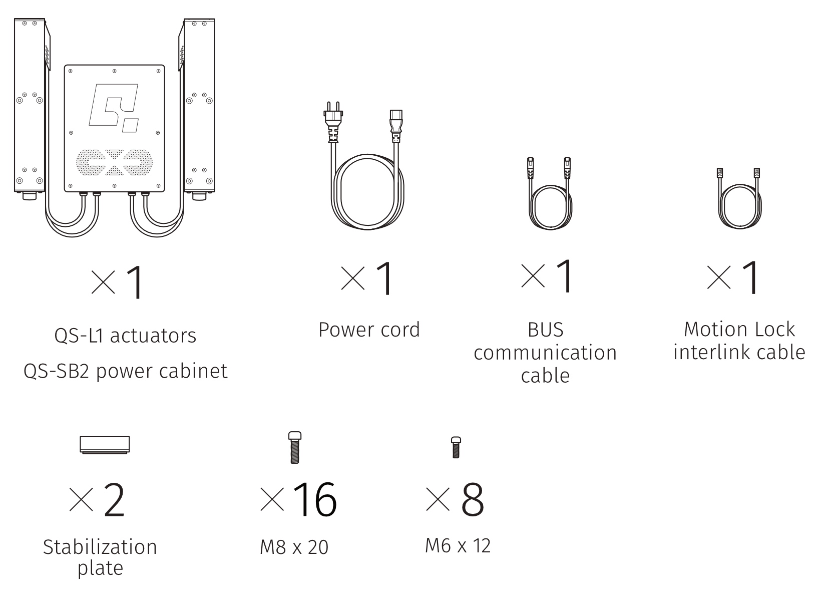
- QS-L1 actuator (x 2) QS-SB2 power cabinet (x 1) Power cord (x 1) BUS communication cable (x 1) Motion lock adapter (x 1)
- Motion link interlink cable (x 1) Stabilization plate (x 2) M8x20 bolts (x 16) M6x12 bolts (x 8)
It can be used to set up various motion rigs (more information about motion rigs in section 3.7.
2.2 Extension set
Info
If you own Intro Set and want to expand your rig and experience by adding a second QS-220-PL please contact the distributor/reseller for more information.
- QS-L1 actuator (x 2) QS-SB2 power cabinet (x 1) Power cord (x 1) BUS communication cable (x 1) Motion link interlink cable (x 1)
- Stabilization plate (x 2) M8x20 bolts (x 16) M6x12 bolts (x 8) Motion lock adapter (x 1)
2.3 Dimensions

2.4 Voltage system
QS-220-PL requires 120/230 VAC single phase with ground and neutral connection.2.5 Grounding requirements
Info
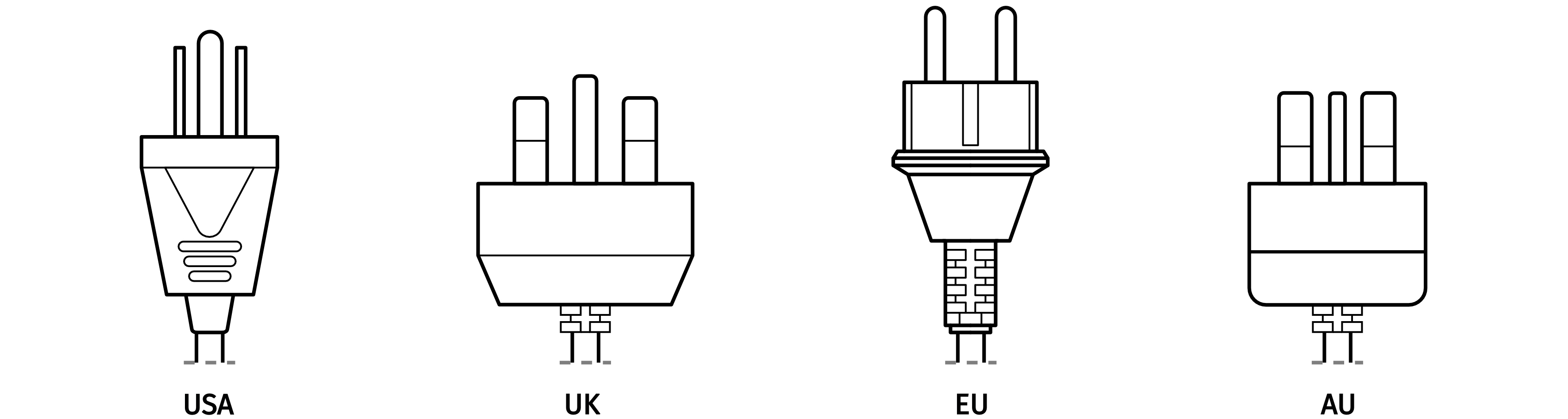
Use only a high-quality power plug adapter purchased from trusted suppliers.
Applicable plugs for different regions:
2.6 Power requirements
Power Cabinet (QS-SB2) contains the power supply for connected actuators. If there is no certainty if fuses or entire electrical installation can handle QS-220-PL, contact a qualified electrician. Be aware that with heavy payload, and/or more intense simulations average power consumption may rise.Warning
For safety reasons, Do not attempt to modify machines or cables by yourself. QS-220-PL can be used in 120V AC/230V AC, 50~ 60Hz environment. Remember to use adequate cables with proper grounding in each case!
Warning
Always UNWIND THE CABLE COMPLETELY when using a cable reel and untangle an extension cord before connecting the device to the power supply.
Warning
Check if the power cord plug has grounding connection (with 3 pins). In order to reduce risk of electric shock Do not use plug without grounding connection (without center pin).

Info
If motion rigs with two Power Cabinets (4 Actuators Setup) are connected to 120V then each Power Cabinet should be connected to the different wall socket with separate fusing - it might be required, to ensure trouble-free work of the QS-220-PL. The grounding point shall be common.
2.7 Cold start procedure
For safety reasons, and in strict compliance with the requirements of ISO 14118:2017 (E) concerning the prevention of unexpected start-up, QS-210, QS-220, QS-V20, QS-CH2, and QS-S25 motion systems require one complete cycle of the Motion Lock switch whenever power is restored after being cut off or during the start-up. Follow the steps below:- Verify that the motion platform is OFF - the power switch on the Power Cabinet is not backlit, and QubicManager displays an Offline status.

- Turn the Power ON. The platform will not move.
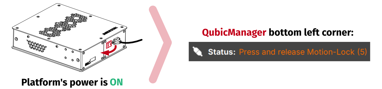
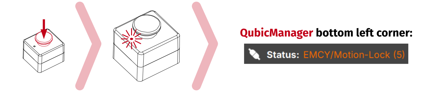
- Press the Motion Lock button - diode emits constant light. The platform will not move.
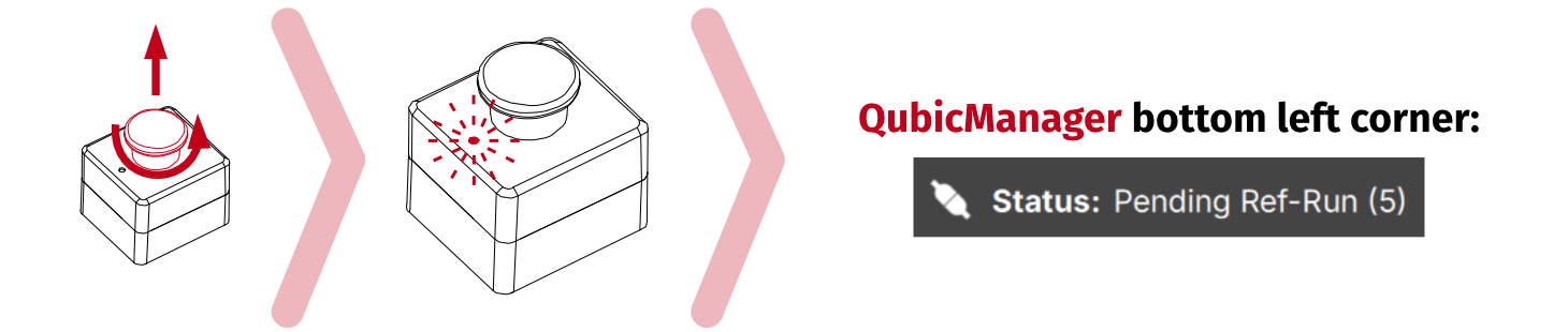
- Turn the Motion Lock button counterclockwise - diode blinks. The system will perform start-up calibration. Do not change the payload.
- If the status displays Parked/centered or Running - the motion platform is ready for operation.
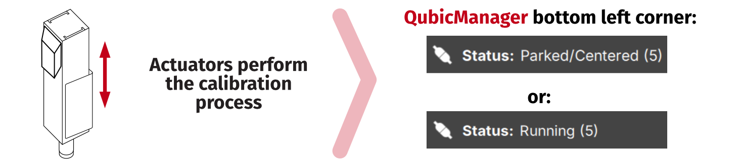
Info
- If the status displays - no need to perform a Cold start procedure, the platform is ready for operation.

- If the platform was already powered ON while starting the QubicManager and status displays - start from step 3.

- If the Motion Lock was already engaged during start-up and the status displays - no need to cycle through the stages, start from step 4.

- For the procedure to work, M10 controller must be powered on (via USB) - QubicManager does not have to be running.
3 Setup and installation
3.1 Before QS-220-PL Installation
Qubic System DOES NOT approve exceeding or ignoring any of the points below and IS NOT responsible for malfunctions, failures or injuries that are results of these actions :Danger
Warning: Dangerous voltage level may occur in the QS-SB2 power cabinet and connected cables during the operation and for a few minutes after turning off the machine. Do not touch the device when the power switch is on.
Warning
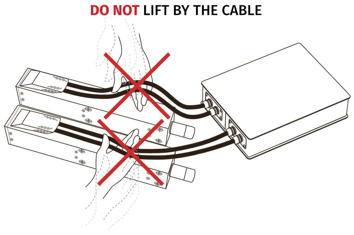
- Cables must not be stretched and should be kept in a way that prevents them from getting under the actuator or any part that can crush or tear them.
- Do not place down the actuators on the cable side on any surface, always place them down with cable side up to avoid cable damages.
Warning
- Each Actuator has to be used with the Stabilization Plate and should be placed on a flat surface.
- Do not use the actuators on very soft or fragile surfaces like rubber, glass, or foam.
- Be aware that QS-220-PL will crawl a little in every direction during operation. Those movements could damage the surface in the long term. The manufacturer, its subsidiaries and their partners, are not responsible for any floor damages.
- Do not mount the rig in tight or cluttered spaces – remember that actuators set motions to the rig and nothing should restrict its motion range.
- Seat belts and other harnesses should be mounted as part of the motion rig that move in the same way as the seat. Do not attach them to any static part or ground.
- If you want to use the QS-220-PL in an unusual application, and you are not sure, that the desired setup is feasible, contact the distributor/reseller.
3.2 Intro Set: QS-SB2 connection - 2 Actuators
To connect QS-220-PL apply following steps: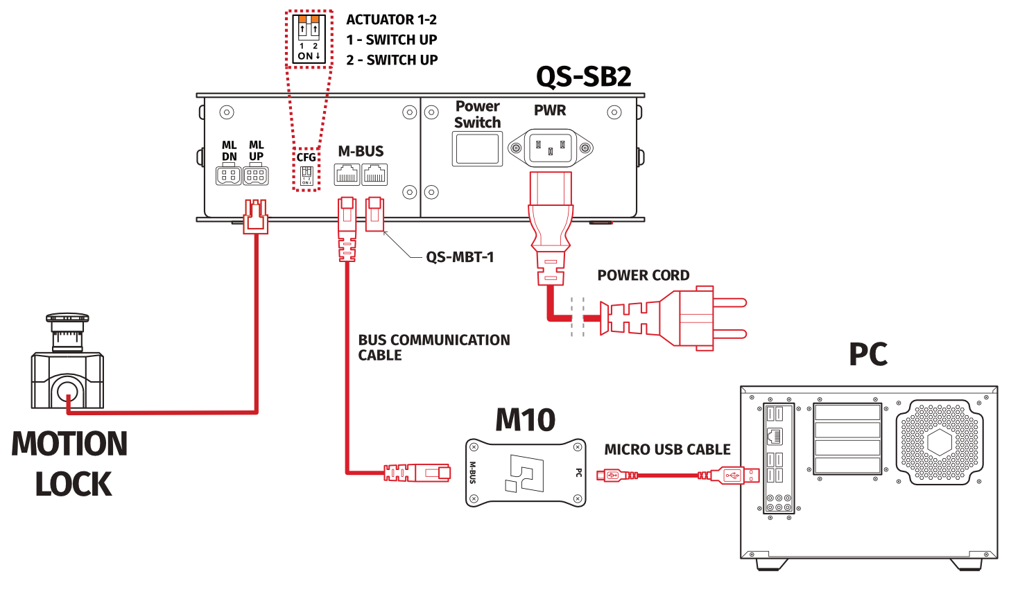
- Plug in the Motion Lock with Motion Lock adapter into Motion Lock "ML UP" port in the QS-SB2 Power Cabinet.
- Connect M10 to M-BUS port in Power Cabinet using BUS communication cable at both ends.
- Put QS-MBT-1 BUS terminator (RJ45 plug with resistor) in second M-BUS port in the QS-SB2 Power Cabinet.
- Connect PC to the M10 controller using USB – micro USB cable (2.0 or newer)
- Plug in the power cable with adequate type of plug into power socket in the QS-SB2 Power Cabinet.
Info
Order of connecting the cables is not important, keep the CFG switches according to appropriate layout.
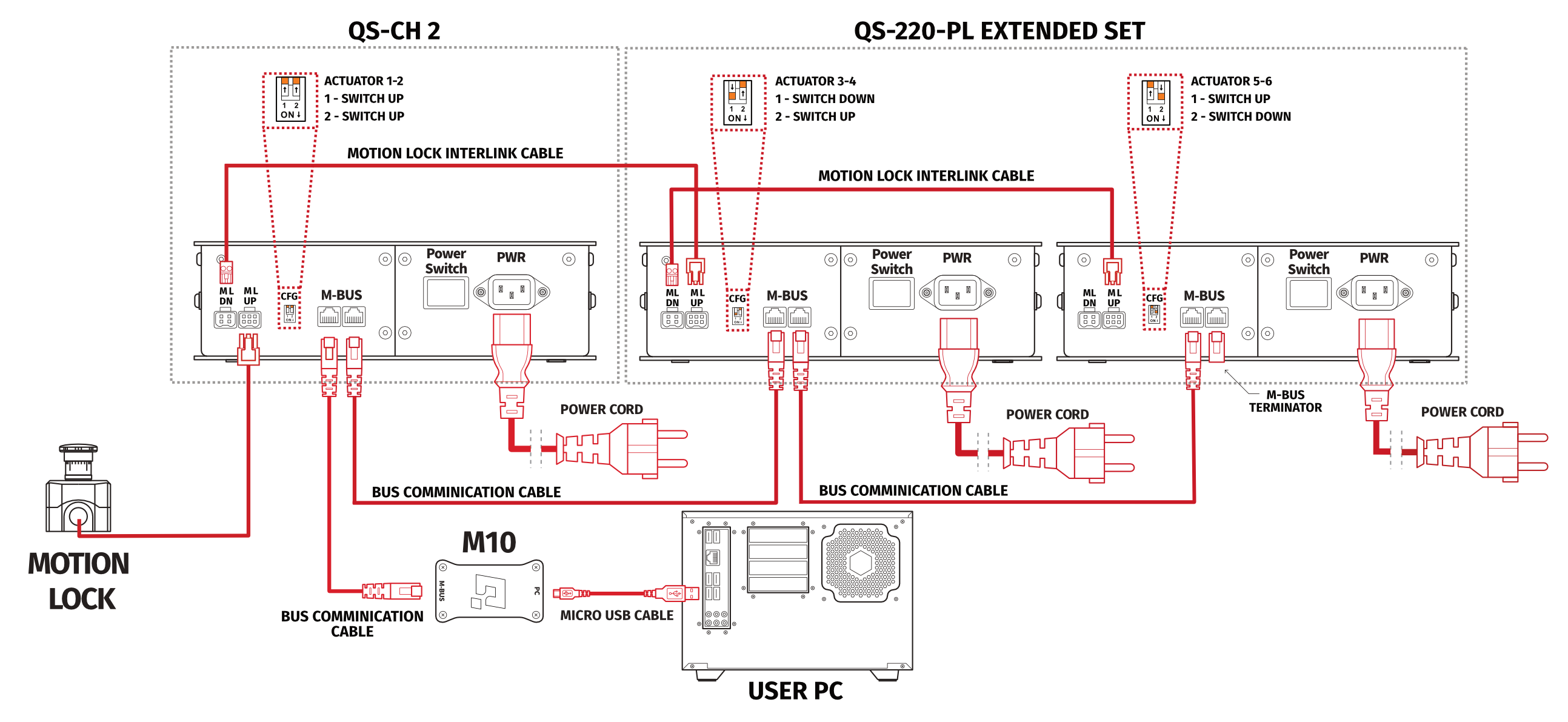
3.3 Extended Set: QS-SB2 connection - 4 Actuators
In rigs with 4 actuators, both Power Cabinets have to be connected to each other, connect them by applying following steps: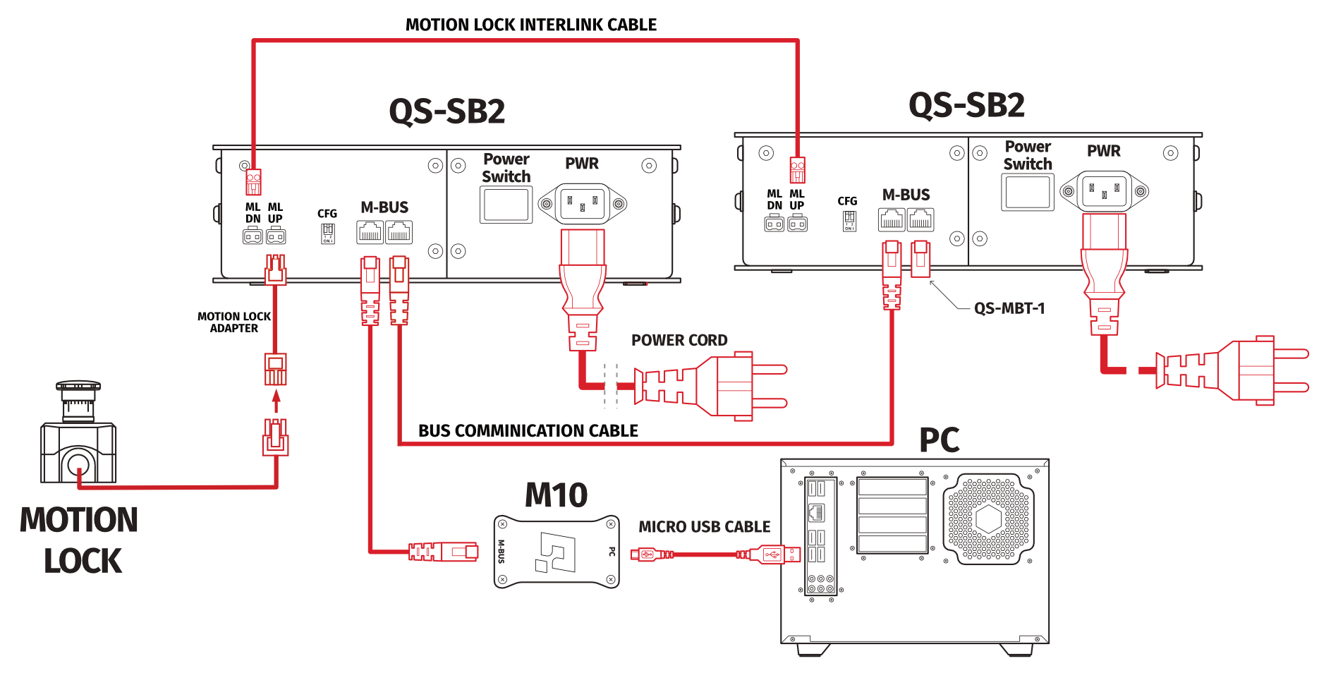
- Plug in the Motion Lock with Motion Lock adapter into Motion Lock "ML UP" port in the QS-SB2 Power Cabinet.
- Connect Motion Lock "ML DN" port from the first QS-SB2 to Motion Lock "ML UP" port in the second QS-SB2 power cabinet using motion lock interlink cable.
- Connect M-BUS ports in both power cabinets using BUS communication cable.
- Put BUS terminator (QS-MBT-1) in the last M-BUS port in second Power Cabinet.
- Connect M10 to M-BUS port in the QS-SB2 power cabinet.
- Connect PC to the QS-220-PL using USB – micro USB cable (2.0 or newer) and M10 connector.
- In both power cabinets, plug in the power cables with adequate plugs into power sockets.
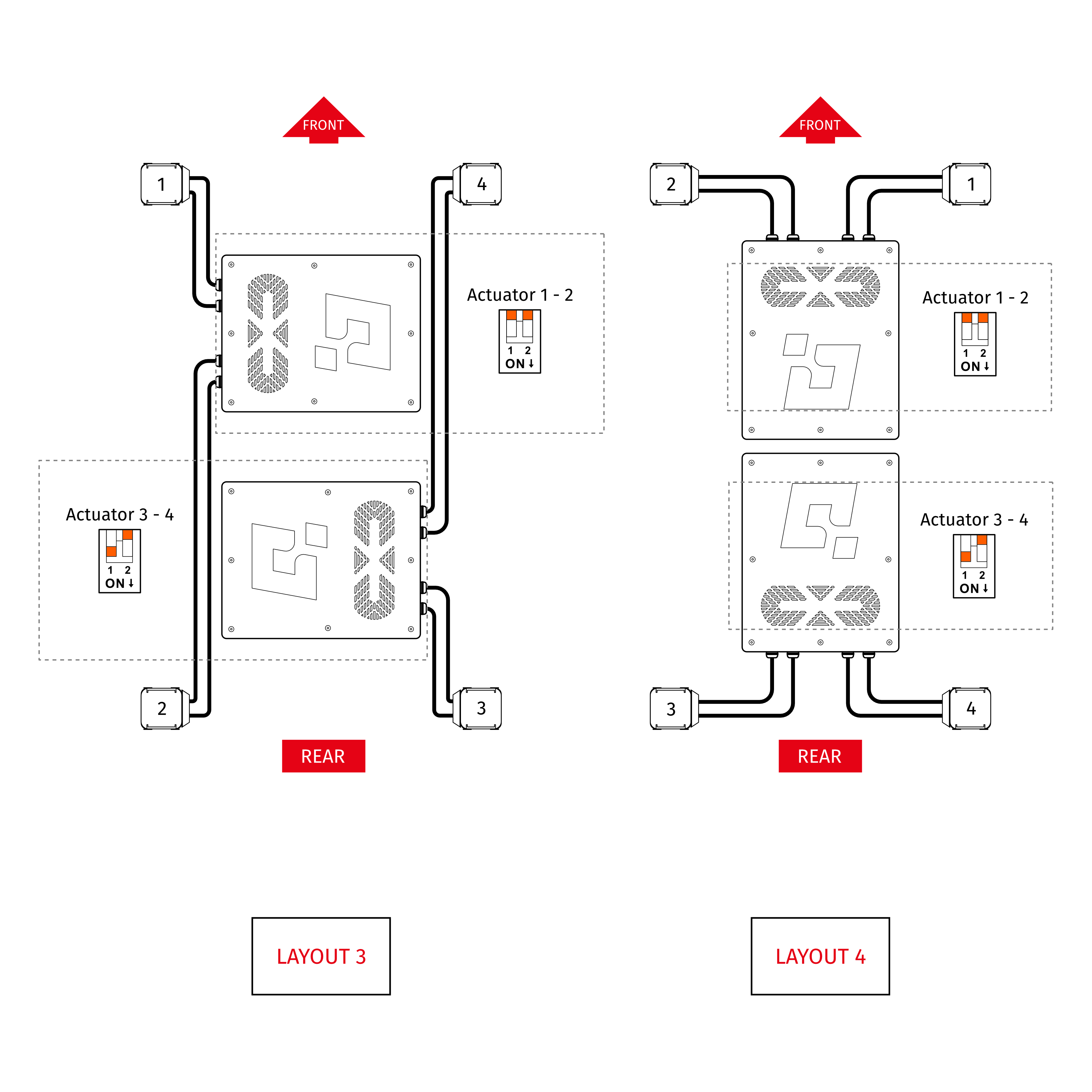
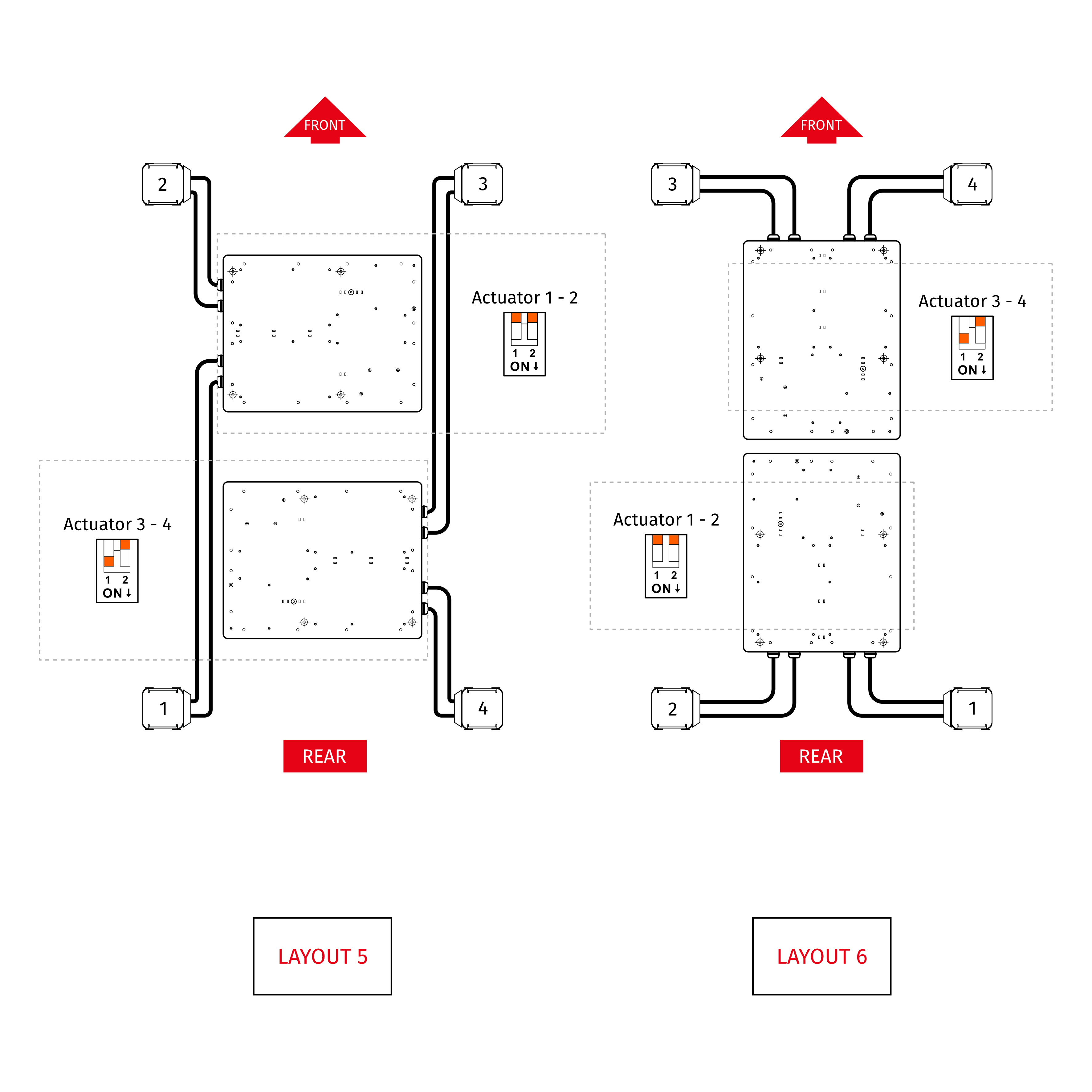
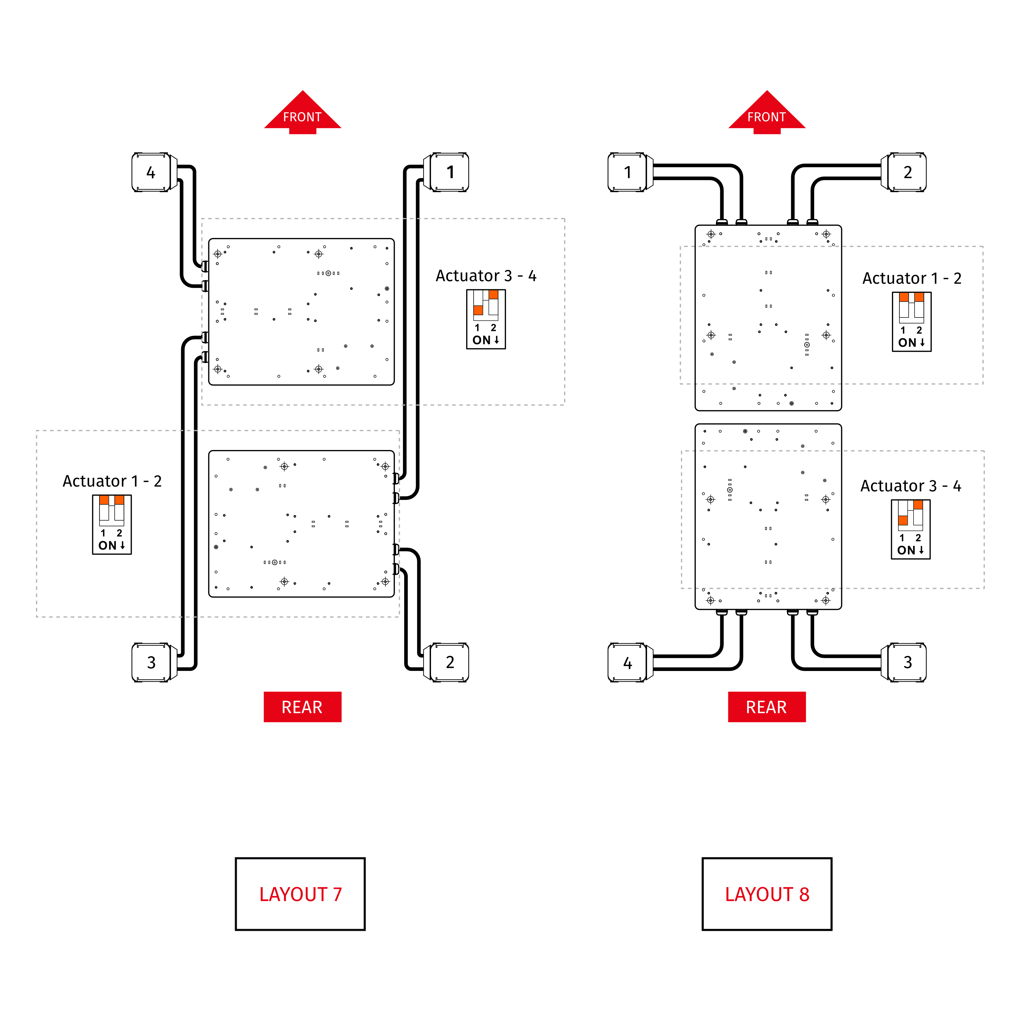
- Set the appropriate position on the CFG Switch according to the actuators layout of your choice (more information about CFG Switch position and layout selection in section 3.6).
Info
Order of connecting the cables is not important, you can connect the M10 controller or Motion Lock to either of the QS-SB2 power cabinet. Keep the CFG switches according to appropriate layout.
3.4 Extended Set: connection with traction loss system
- Plug in the Motion Lock Switch into the "ML UP" port in the first QS-SB2 power cabinet.
- Connect Motion Lock "ML DN" port in the first power cabinet to Motion Lock "ML UP" port in the second power cabinet using motion lock interlink cable.
- Connect Motion Lock "ML DN" port in the second power cabinet to Motion Lock "ML UP" port in the third power cabinet using motion lock interlink cable.
- Connect M-BUS ports in all power cabinets using BUS communication cable.
- Put QS-MBT-1 terminator in the last M-BUS port in the third QS-SB2 power cabinet.
- Connect M10 to the first M-BUS port in first QS-SB2 power cabinet.
- Connect PC to the M10 controller using USB cable.
- In all power cabinets, plug in the power cables with adequate plugs into power sockets.
- Set the appropriate position on the CFG Switch as shown on the connection scheme.
Info
3.5 Intro Set: layout setup
For the Intro Set (2DOF) layout setup must be done using QubicManager Software - Hardware Configuration panel (check item itm:Correct Setup Layers 2 Actuators).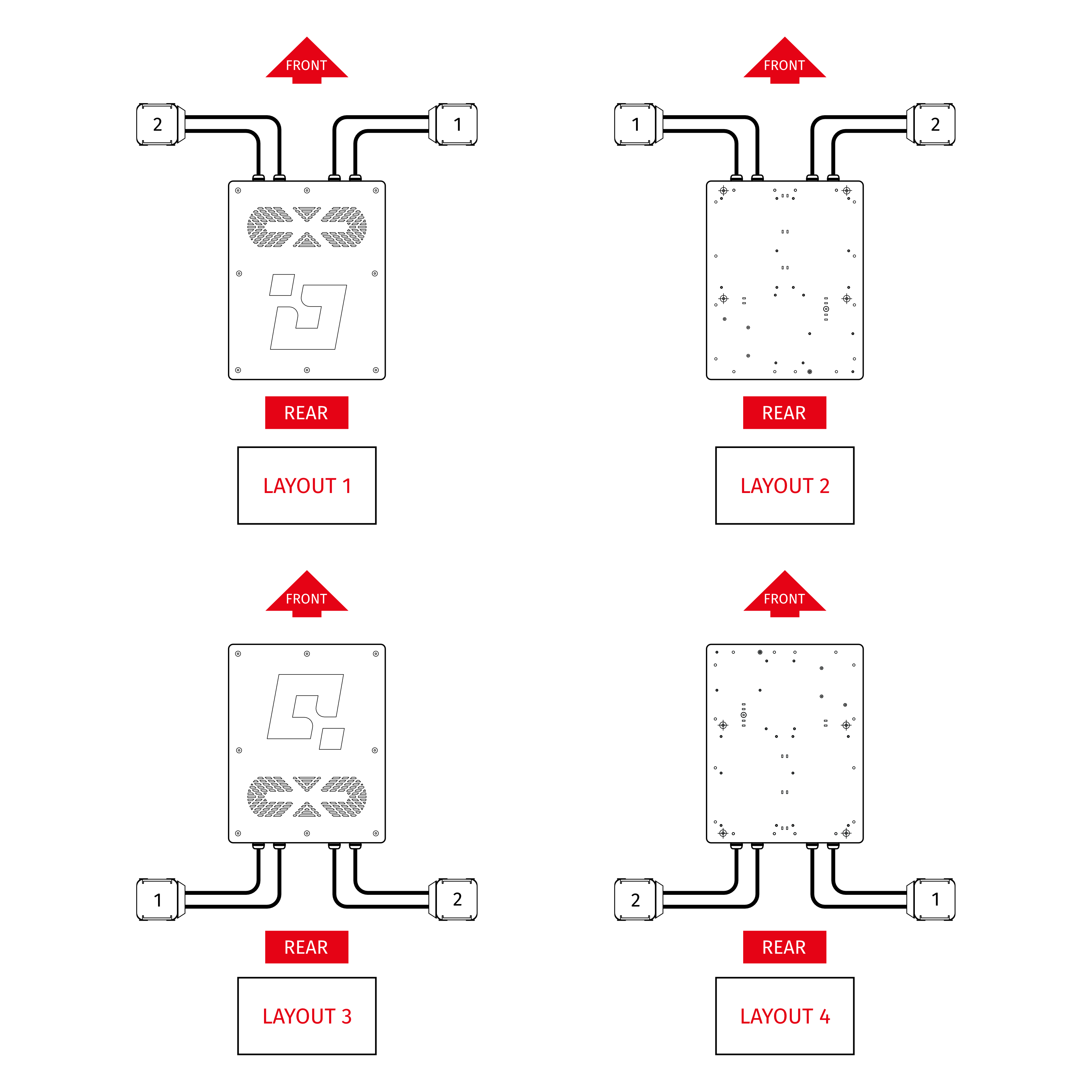
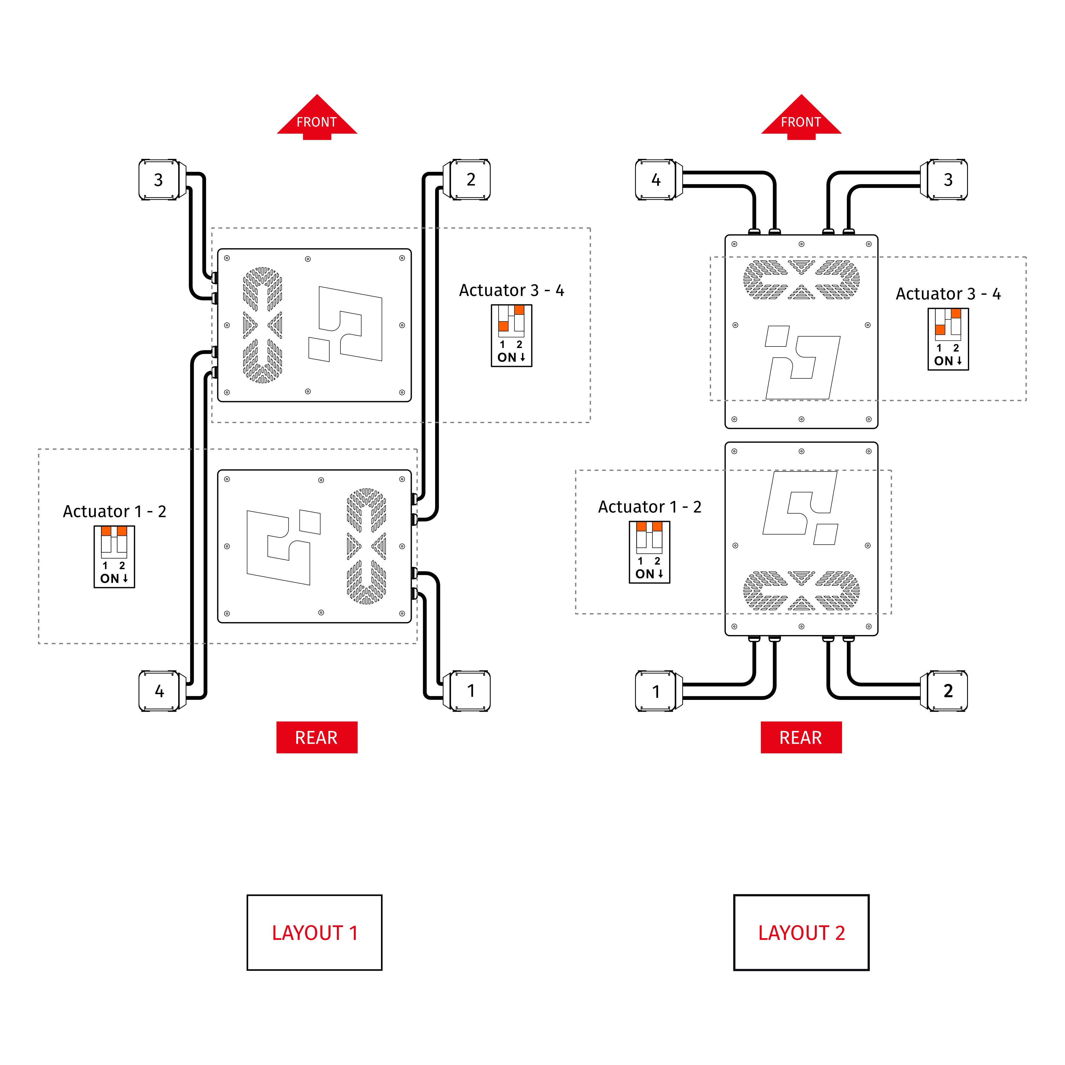
3.6 Extended Set: layout setup
Start the configuration by setting the CFG Switches to the appropriate positions in accordance with one of the eight variants of the power cabinets and actuators installation to the cockpit. Go to QubicManager→Tools and Diagnostics → Devices and select Configure (check point itm:Correct Setup Layers 4 Actuators).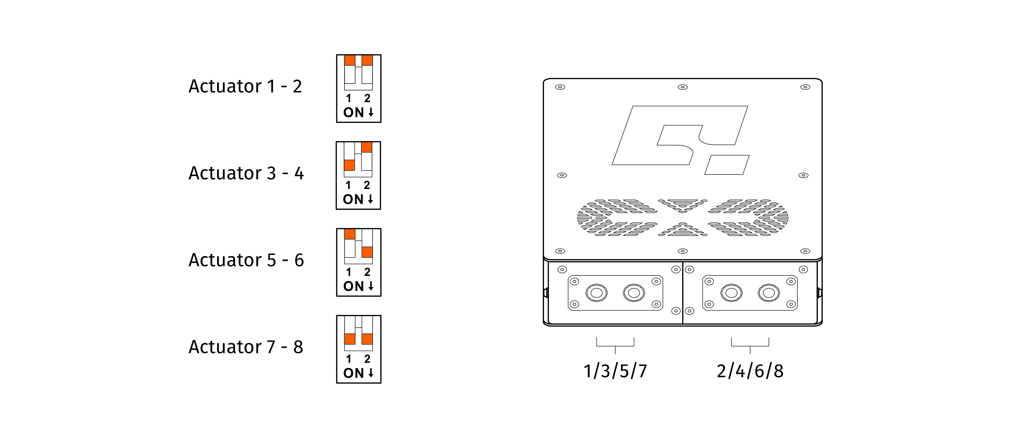
Warning
The CFG Switch CAN NOT be set in the same position in both power cabinets.
Warning
When changing CFG Switch setting the main power must be SWITCHED OFF.
Warning
When changing the CFG Switch setting FIRMLY SET THE SWITCH into lower or upper position. Do not leave the switch in the floating position (neither up or down position), otherwise the device will not work.
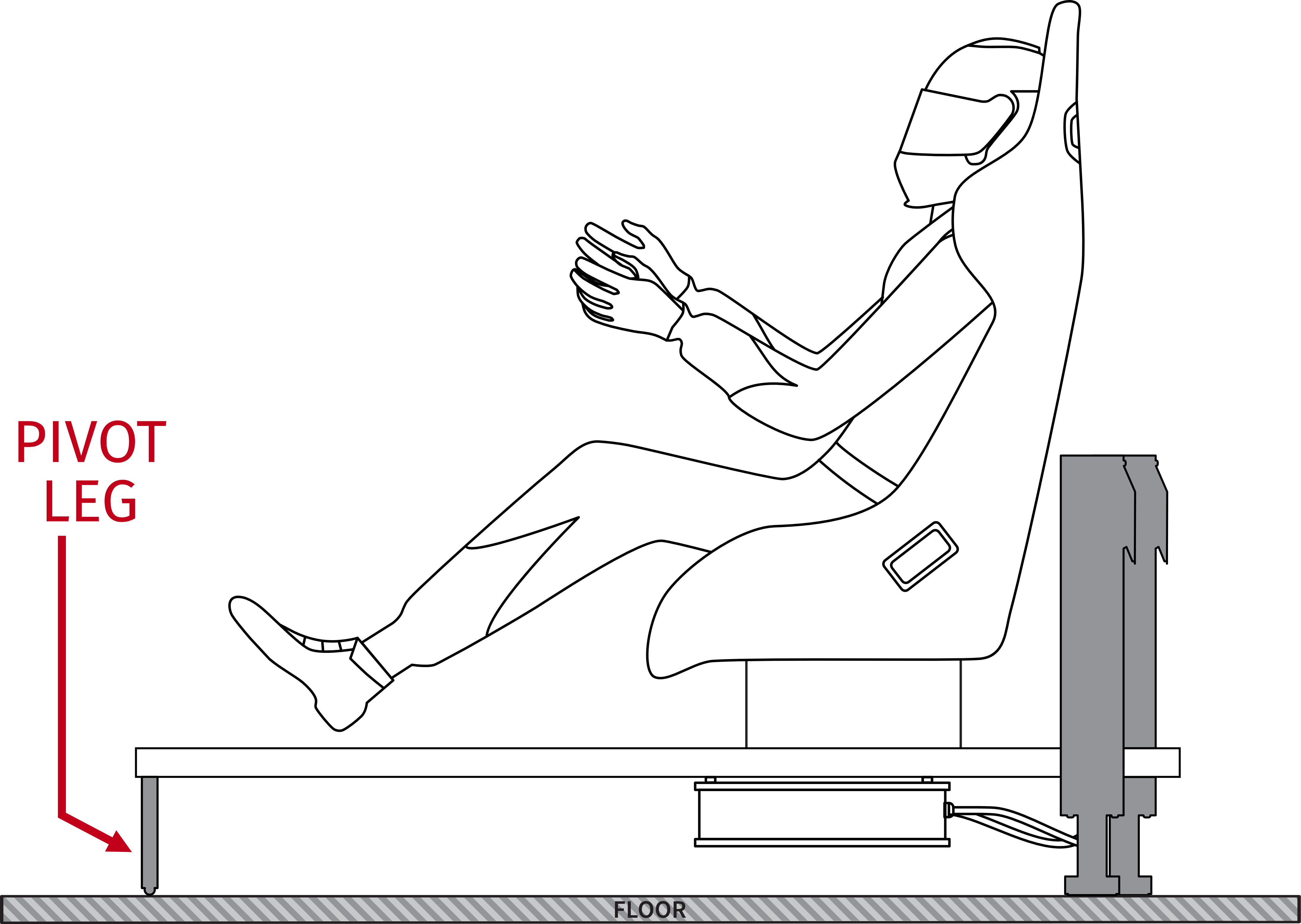
3.7 QS-220-PL Assembly Instruction
Info
Before mounting the rig, check if the QS-220-PL is working properly. Check the positioning of the actuators and their numeration.
- Actuators should be connected to the motion rig with 8 screws (M8x20) each.
- Power Cabinet has to be mounted using at least 4 screws (M6x12) – we recommend mount it in the middle of the motion rig. It is possible to mount the power cabinets using the bottom or side mounting holes. Check section 2.3.
Warning
Ensure that the Power Cabinet does not have a collision with the floor in any position of motion rig.
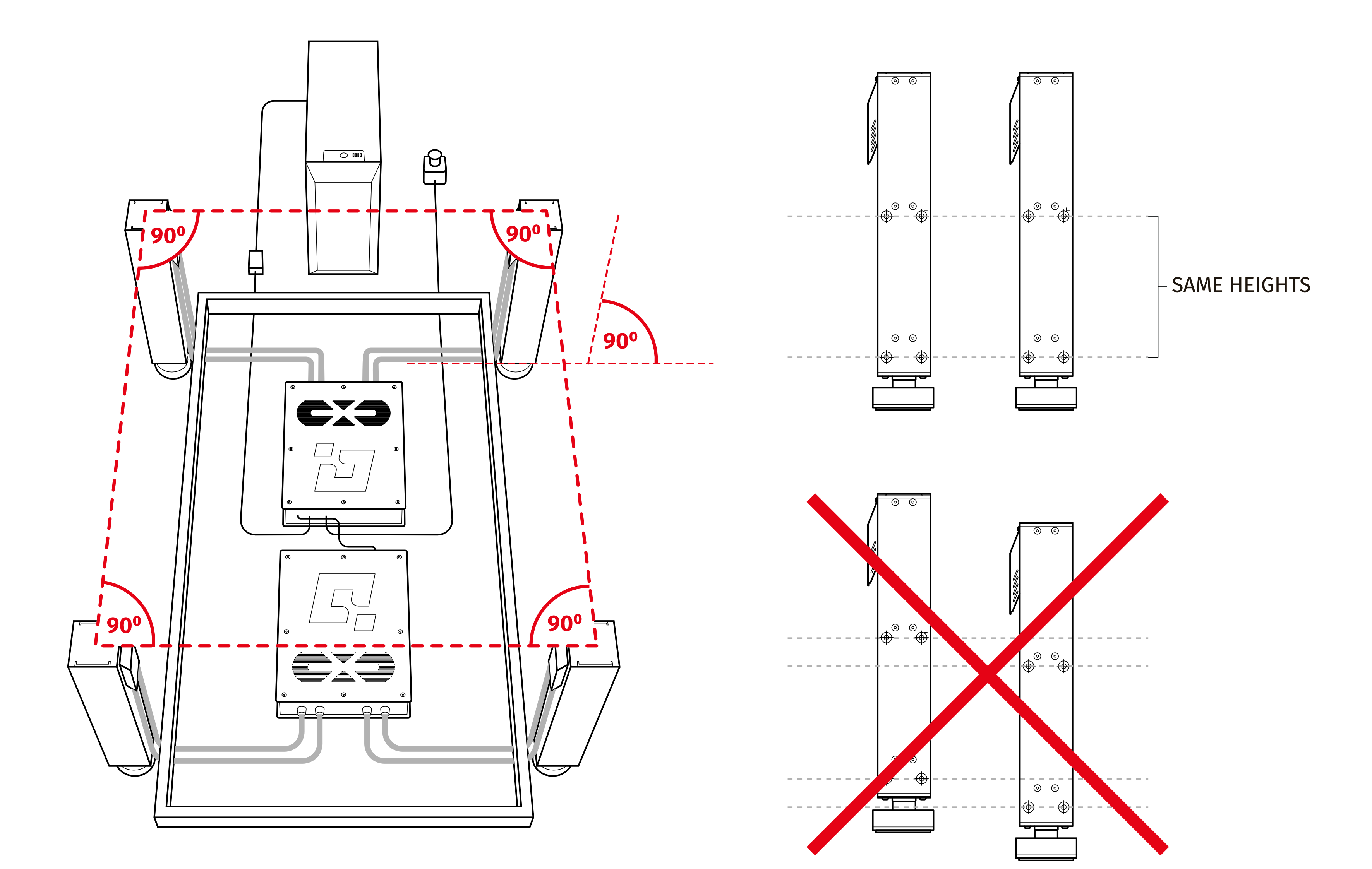
Warning
Ensure that Actuators are mounted at the same height.
Info
3.8 Software Installation
Info
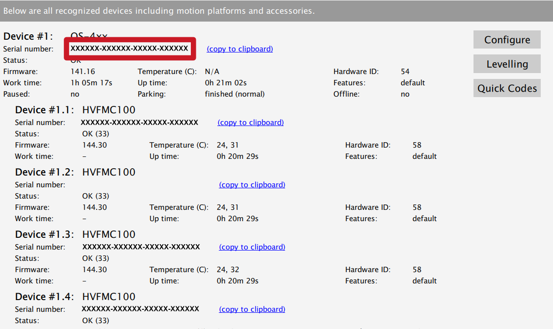
Note down the QS-220-PL serial number before installation as it's needed to access software download page.

To download the software visit : QubicSystem.com/Download
Once the QS-220-PL is installed and connected correctly:
- Connect power connection cord to the wall socket. If you own extended set connect both power cords.
- Download QubicManager.
- Proceed with the installation steps and launch the application.
- Turn on the system by switching on the power switch button on the QS-SB2 power cabinet (on both if you own extended set).
- Check position of Motion Lock Switch, unpress if needed.
- The QS-220-PL will perform a start-up calibration.
WarningDo not change the payload during the start-up calibration.
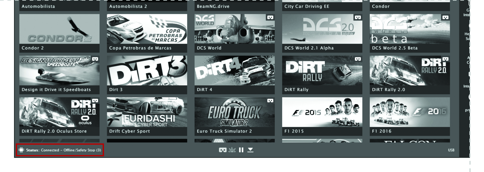
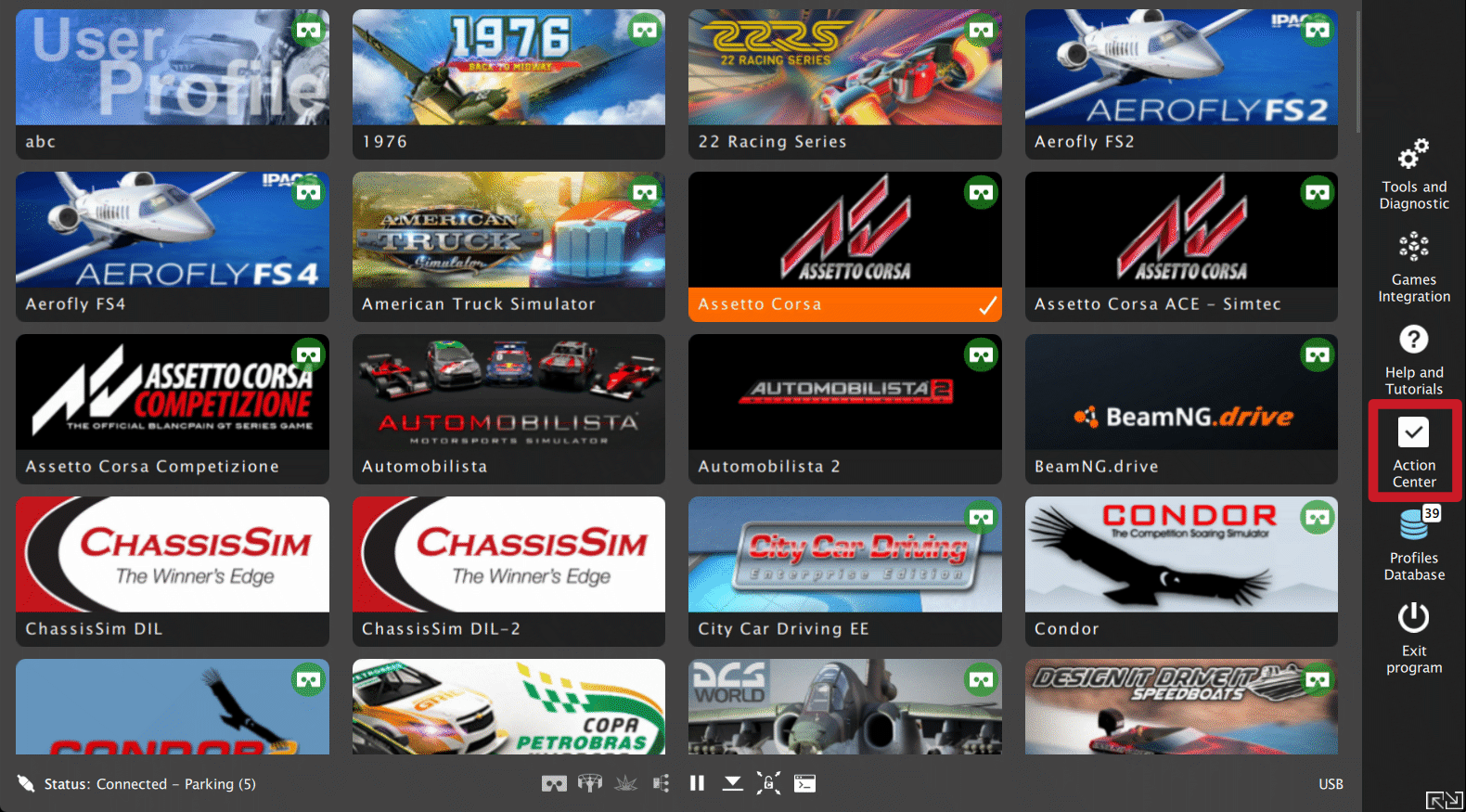
- If QubicManager has recognized the QS-220-PL correctly, the status of the machine visible in the lower left corner will change to Connected.
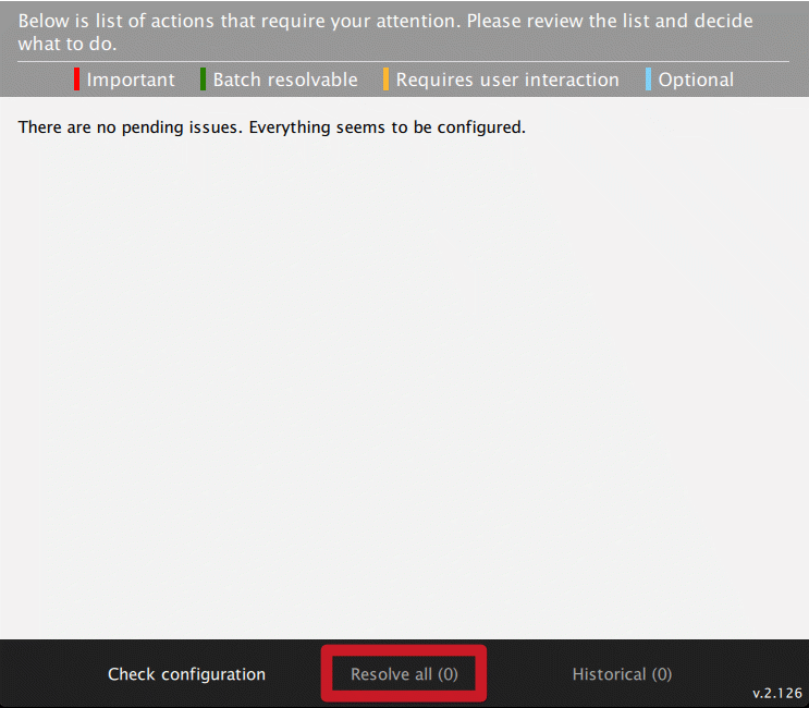
- Check Action Center on the right side panel for a list of actions that requires attention:
It is possible to solve them one by one or by pressing the Resolve All button. Firmware update may require additional confirmation in the dialogue box.
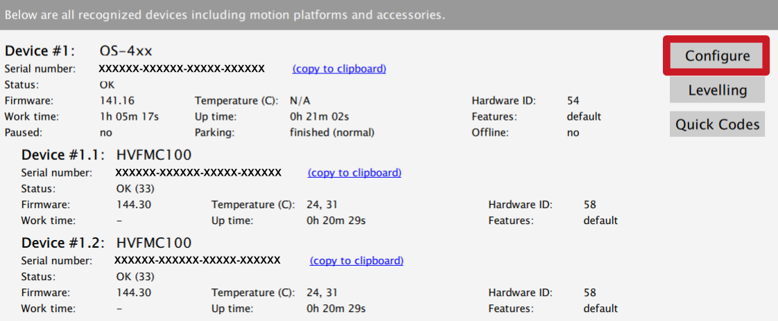
- Go to Tools and Diagnostics → Devices and select Configure.
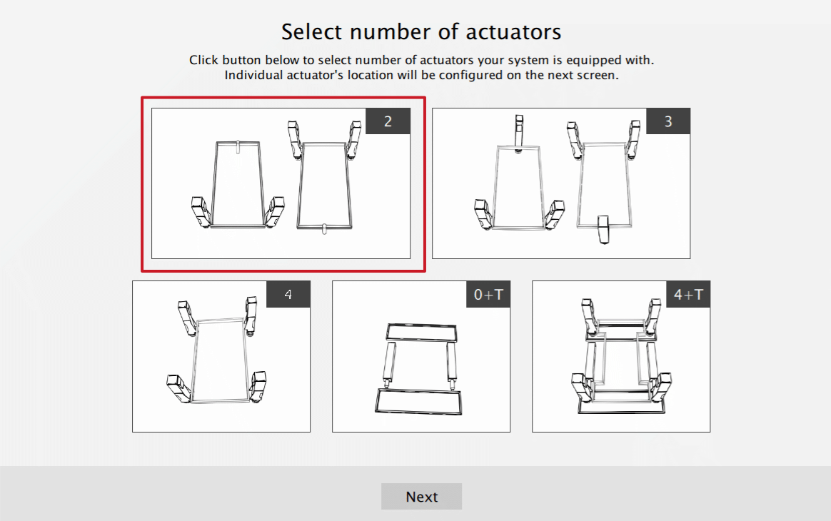
- FOR 2DOF CONFIGURATION (Intro set): Choose the correct layout from the list:
- Measure the distance between front side actuators. Put in the value in the platform dimensions Width field (in millimetres).
- Measure the distance between front side actuators and rear pivot leg. Put in the value in the platform dimensions Length field (in millimetres).
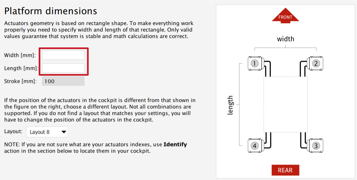
- Scroll down in the window, you can choose one of the operation modes:
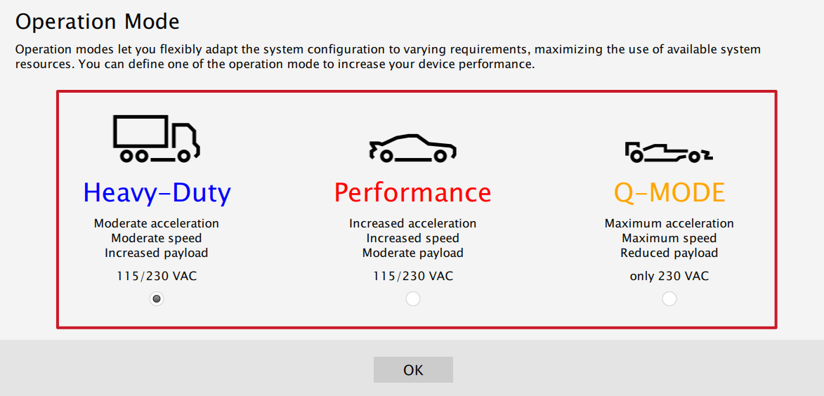 InfoQ-MODE is unavailable for 120V power supply.
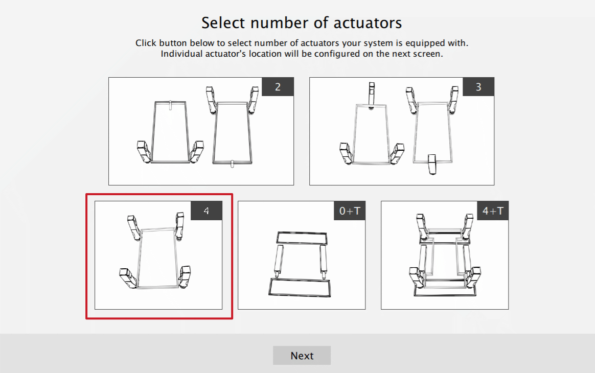
 - FOR 3DOF CONFIGURATION (Extended set): Choose the correct layout variant from the list :
- Measure the distance between front side actuators. Put in the value in the platform dimensions Width field (in millimetres).
- Measure the distance between front and rear side actuators. Put in the value in the platform dimensions Length field (in millimetres).
- Scroll down in the window, you can choose one of the operation modes:
InfoQ-MODE is unavailable for 120V power supply.
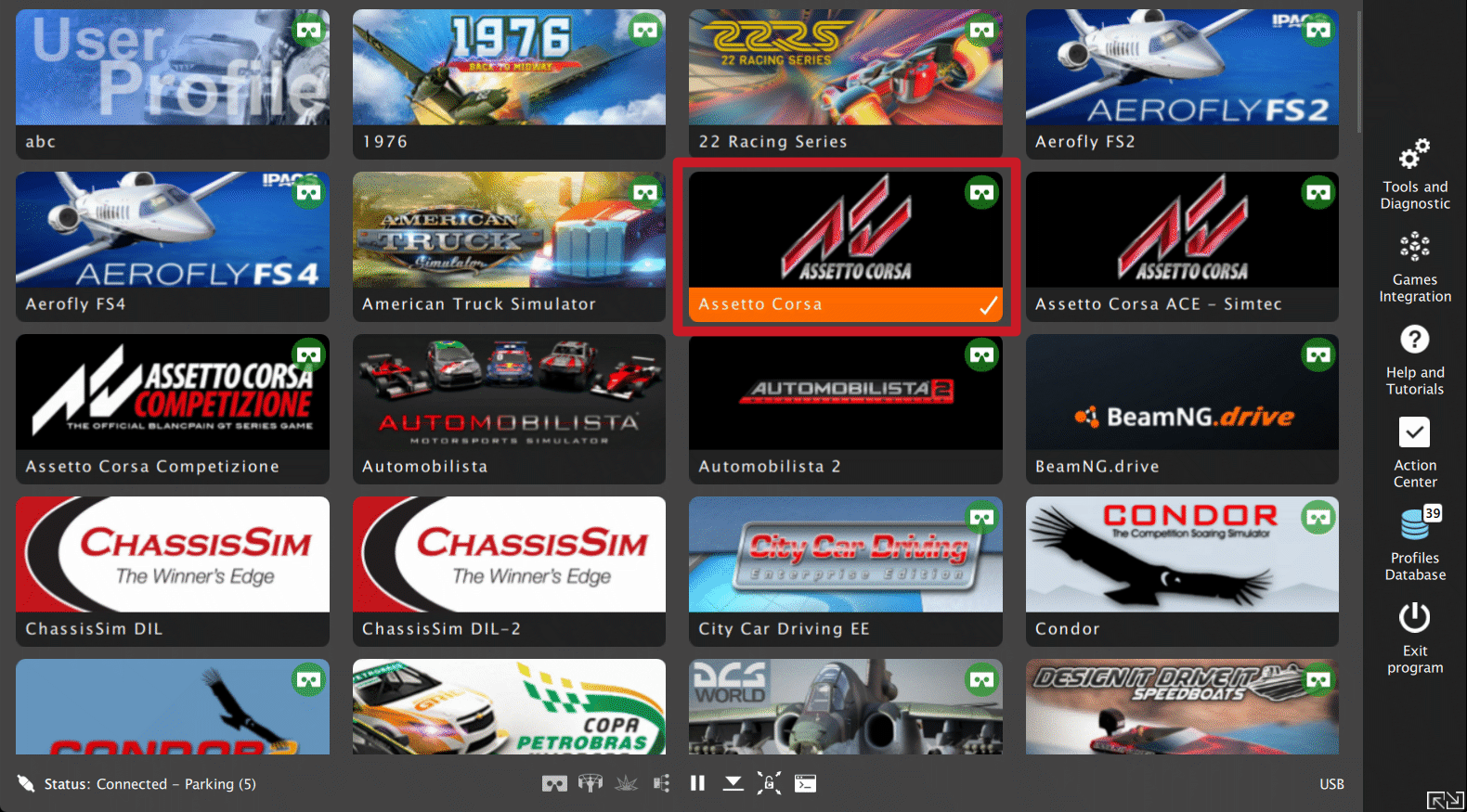
- Close the configuration and return to the main application window. Choose the game and check profile details by clicking on the game tile.
- Adjust the motion effects intensity to your preferences in the game profile window, scroll down in the window to see all of the settings. You can adjust the settings during the game simulation by pressing ALT+TAB.
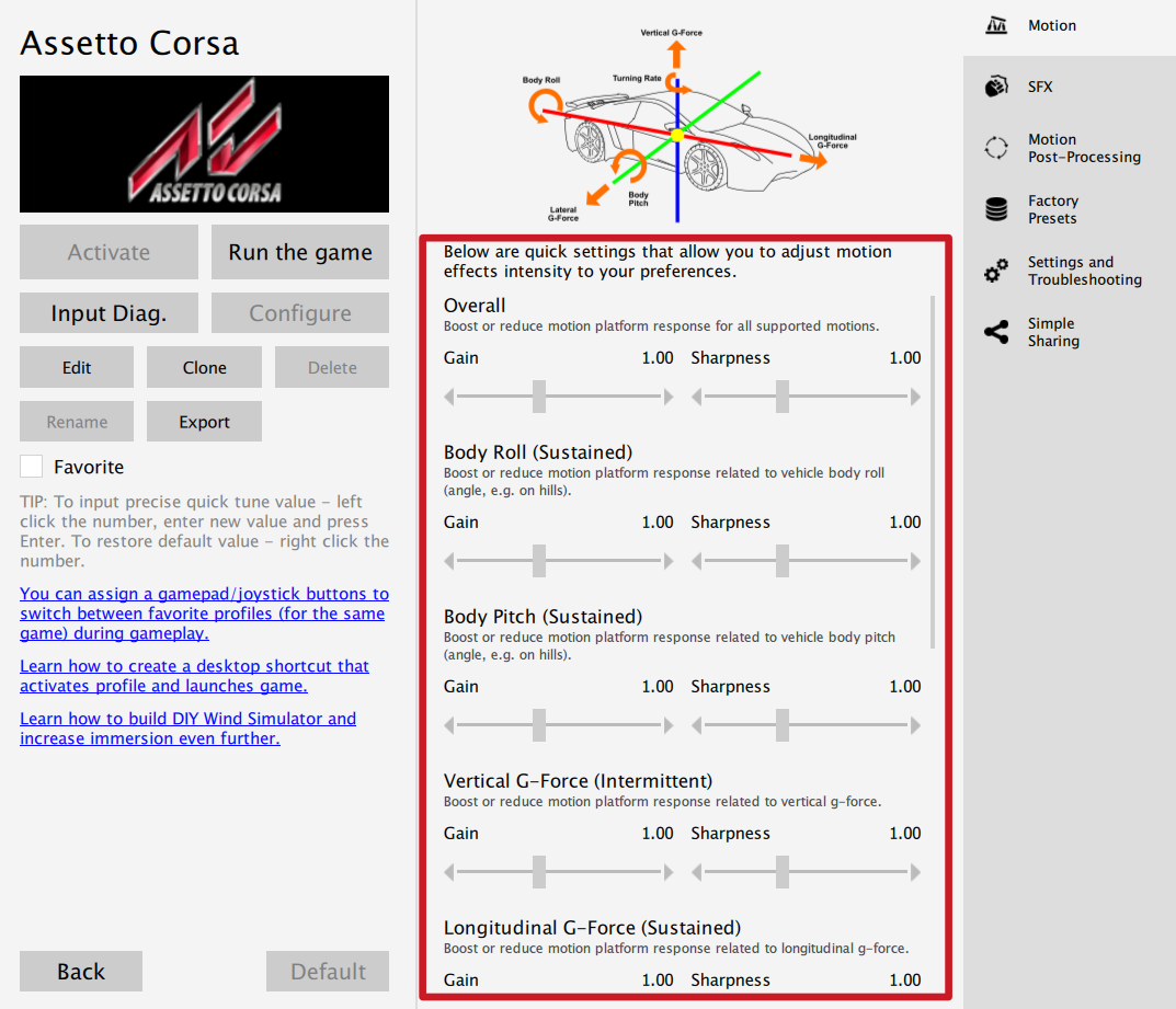
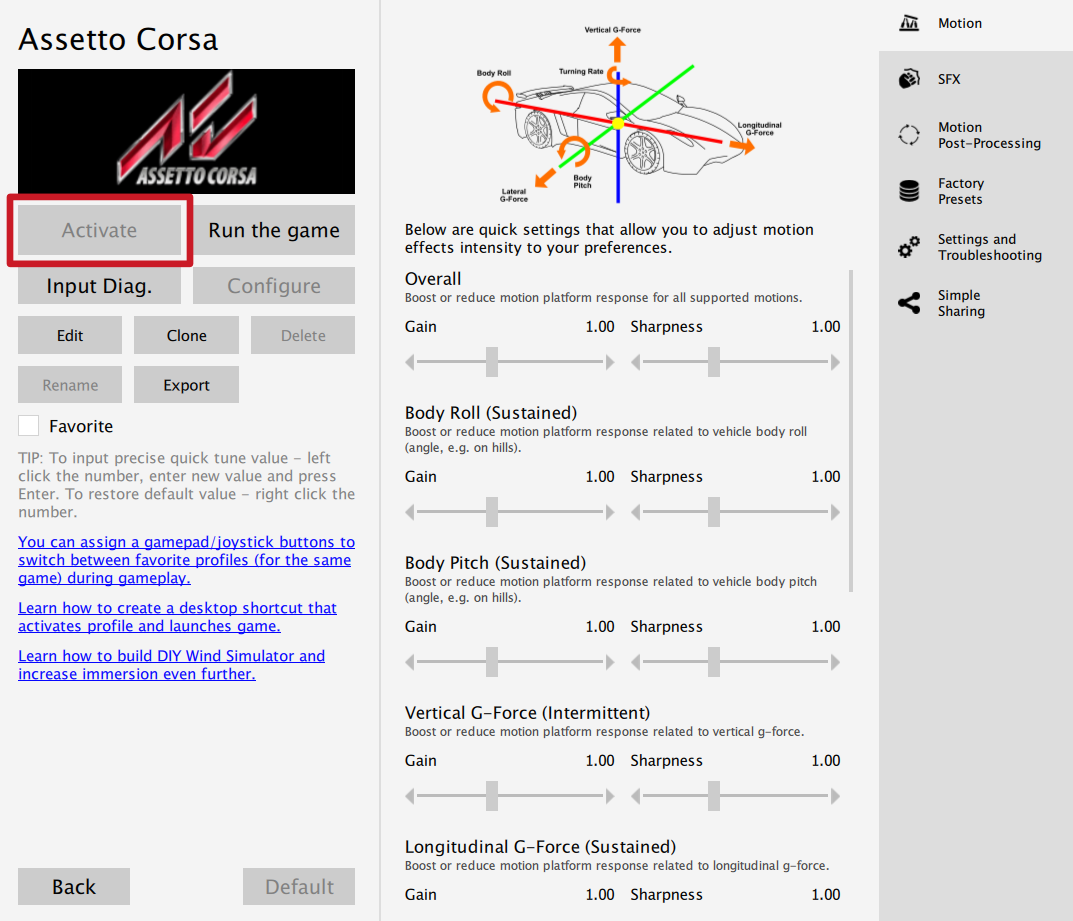
- Activate profile by clicking the Activate button.
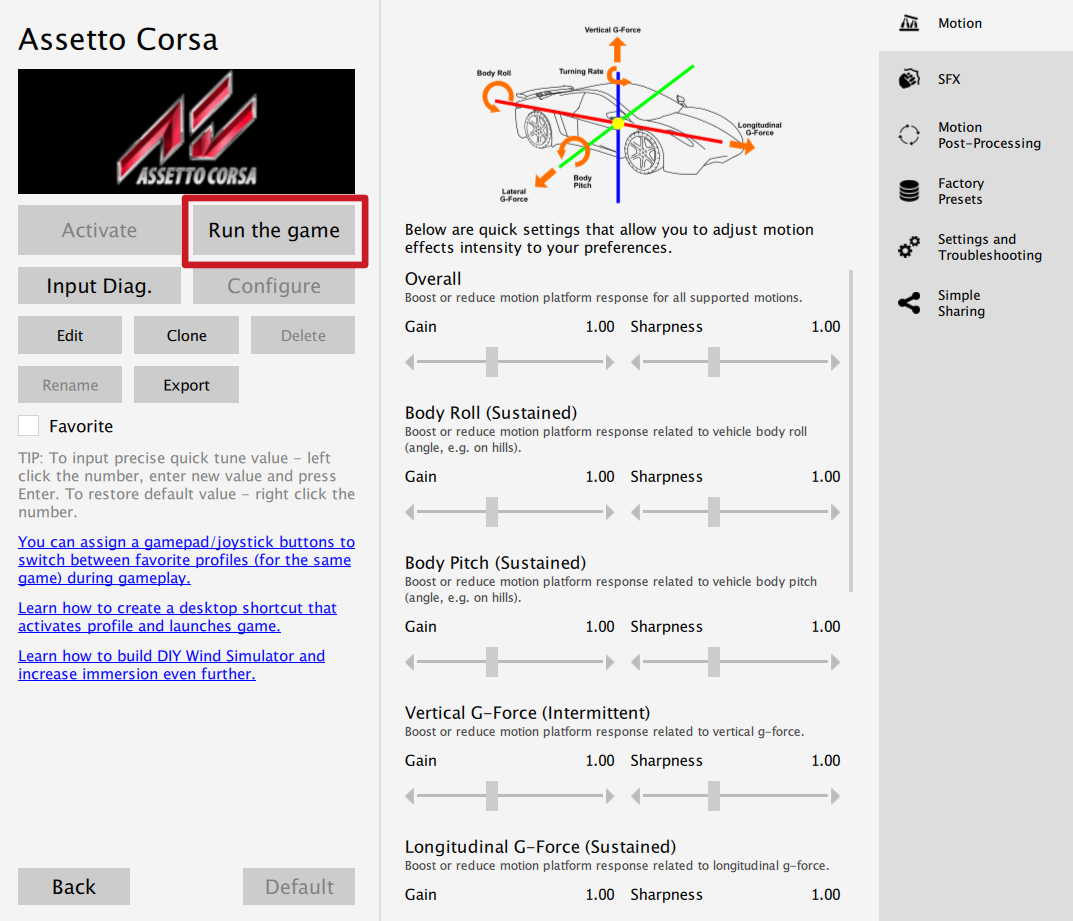
- Launch on the game by clicking the Run the game button.
Info
Warning
The software is provided "as is", without warranty of any kind, express or implied, including but not limited to the warranties of merchantability, fitness for a particular purpose, and non-infringement. In no event shall the authors or copyright holders be liable for any claim, damages, or other liability, whether in an action of contract, tort or otherwise, arising from, out of, or in connection with the software or the use or other dealings in the software. The software sends anonymous usage data to the Motion Systems company. The data is used to improve the software and game profiles. The data is not used for advertising purposes.
4 Maintenance and Cleaning
To minimize the risk of abnormal heating that can result in system failure, keep the QS-220-PL uncovered, clean and dust-free. Cleaning of the unit shall be performed only with a soft, dry cloth. Do not use any chemicals, water and other liquids to clean the device. At least once a month, check if Motion Lock Switch is working correctly – turn on the QS-220-PL (when no one is using the rig) and push the red button. If the machine turns off and does not react to any signal (turn on simulation or game to check it) then Motion Lock Switch works properly. If the machine reacts in any different way, stop using it and contact the technical support immediately. To minimize the risk of QS-220-PL failure, check the condition of the linear actuator's rubber seals once a month, and lubricate them externally, if necessary, using a viscous lubricant spray with dispenser.5 Troubleshooting
Warning
Do not attempt to do any repairs by yourself. It is dangerous and voids the warranty! Repairs should be consulted with technical support and then performed by a qualified technician.
- Check Action Center in QubicManager.
- Check power cables and connection between PC and QS-220-PL
- Check Motion Lock Switch position and its connection cables.
- Try different USB ports.
- If a problem occurred abruptly, it could be caused by thermal protection. Turn off QS-220-PL, disconnect it from power outlets and wait at least 15 minutes to let it cool down.
- In case of every unclear electrical issue like burnt fuses or strange behaviour, contact support.
- If abnormal work conditions, please immediately contact with the distributor/reseller for technical support.
6 Advanced applications
Info
Examples shown in this section describes optional application of external safety and power cut-off devices. If you wish to expand the functionality of your motion system, read the whole section to have a good understanding of how to apply and what functionality to expect. Apply at your own discretion.
Warning
Motion Lock input is not a SIL/PL (safety integrity level/performance level) rated and DOES NOT guarantee safety. If you wish to achieve specific SIL/PL ranking, consider introducing a power cut-off device that is controlled by an external safety relay and cuts off the power to all QS-SB2. Example application of the power cut-off contactor can be found in section 6.3.2 and 6.3.3.
Info
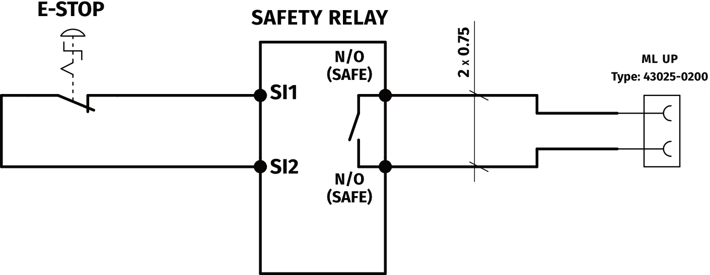
When applying safety relay to the Motion Lock :
- Use input cables according to your safety relay manual.
- Use output cables according to your safety relay manual and cross section
no less than 0,75 mm2
6.1 Adding additional devices to the motion lock circuit
If there is necessity to stop other devices, apart from the QS-220-PL, ML (Motion Lock) and additional customer devices can be controlled by safety relay outputs. In the example application, the E-STOP button is connected to the external safety relay. When the E-STOP is triggered, the safety relay will activate the Motion Lock function, which will stop motion of the platform and additional devices.
Example application of single-channel safety relay that controls ML and additional devices :
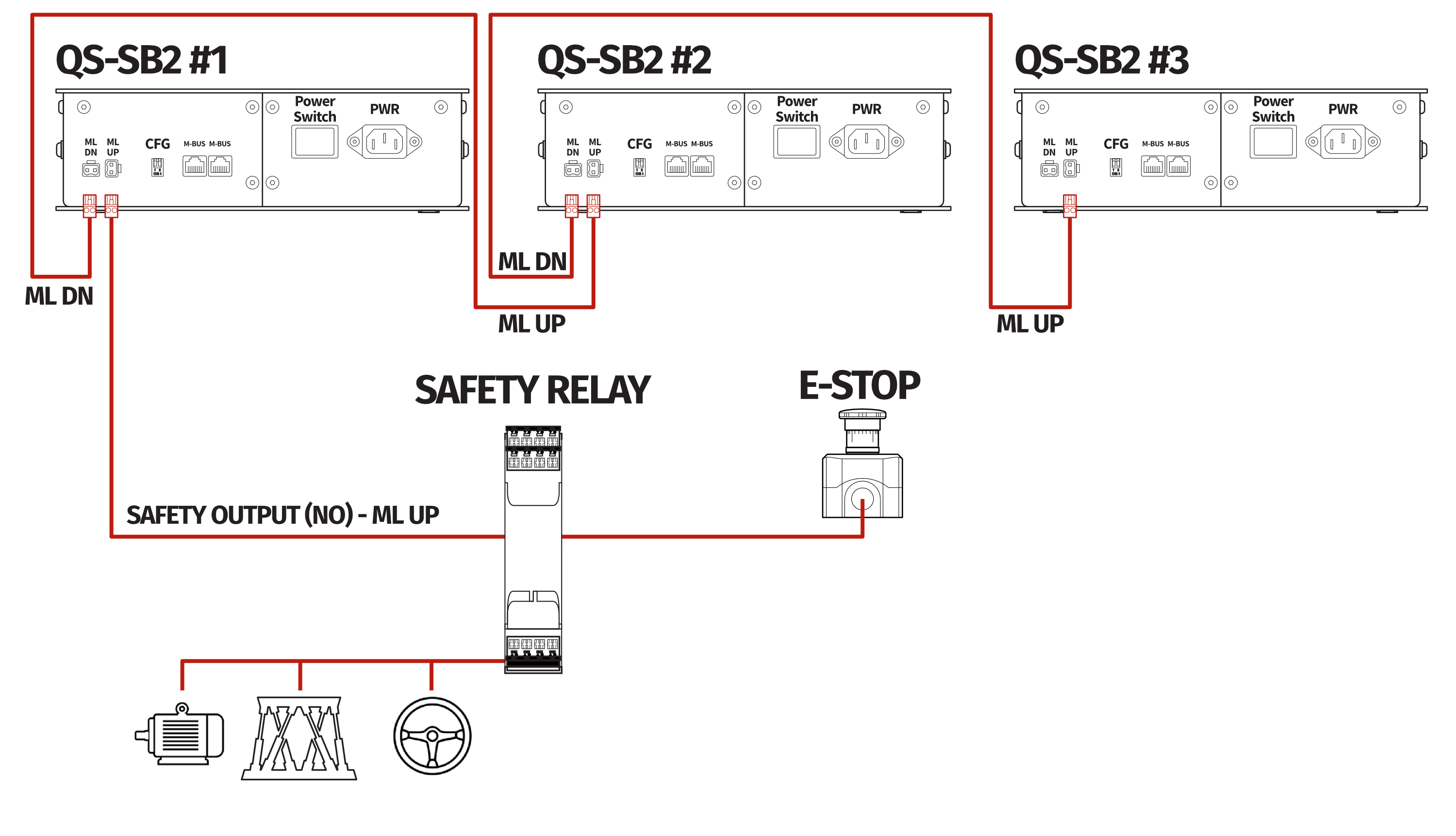
Example wiring diagram of application of single-channel safety relay:
6.2 Implementing the working zone protection
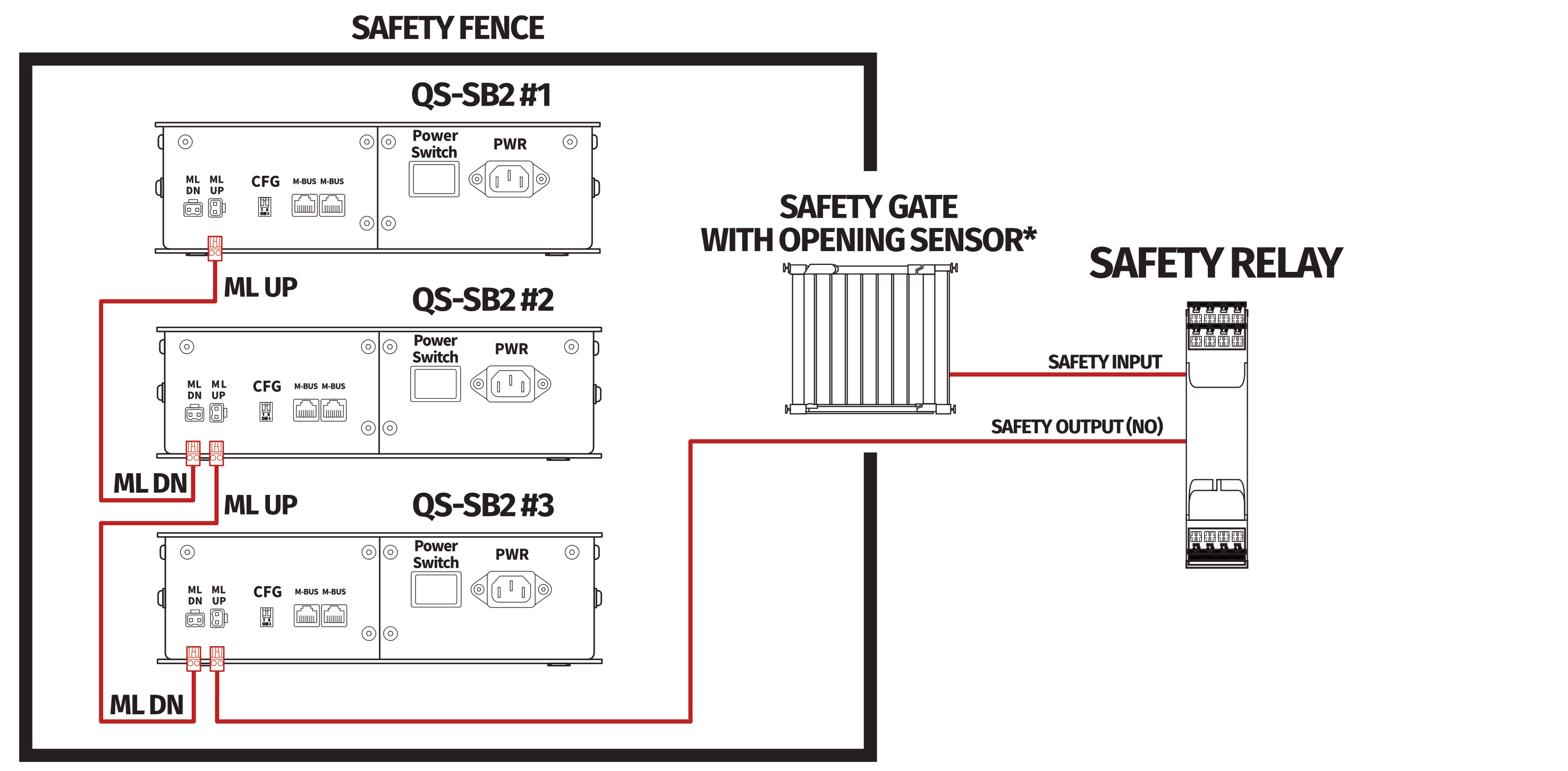
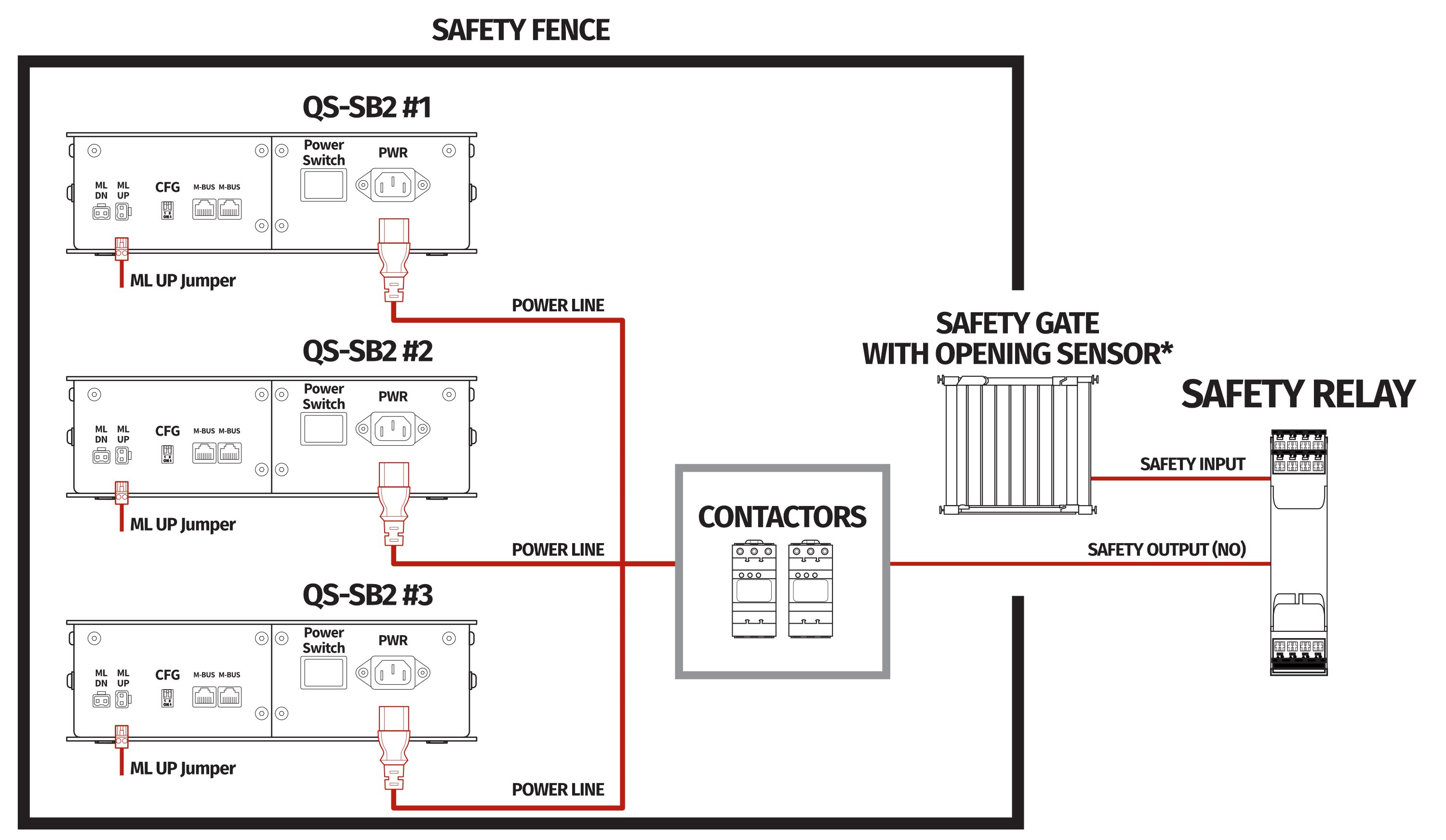
For protection against accidental hit from moving parts of the platform, safety gate with opening sensor* can be connected to safety relay input for activating ML function. When the gate is opened, the safety relay output activates the ML (Motion Lock) function and stops the motions of the platform.
Example application of safety gate opening sensor:
6.3 Increasing safety level
Warning
Modifications of the safety system, involving application of the power line contactors, shall be performed only by a competent person. A competent person is a qualified and knowledgeable person, who because of their training, experience has the knowledge required to apply those changes. It is customer responsibility to commission modification of the safety system to a competent person, experienced with industrial wiring practices, which will be required to undertake the installation. Commissioning shall be undertaken by a trained electrical technician experienced in safety installations.
6.3.1 Assembling Motion Lock jumpers
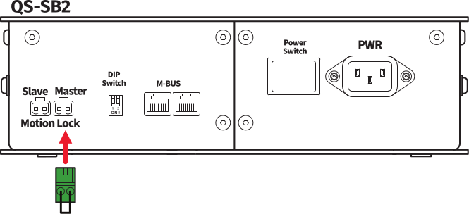
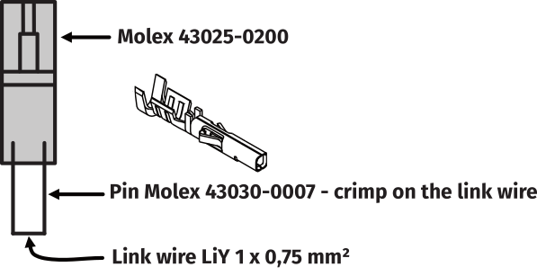
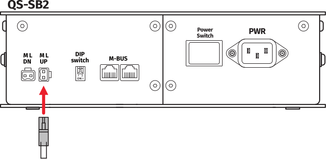
To apply solutions which require to use power line contactors, Motion Lock connection cables in the QS-SB2 power cabinet needs to be replaced with jumpers, which are not provided with the system. Depending on the system revision, there are two types of Motion Lock connections. To prepare jumpers, you need to assemble recommended connectors as shown below, depending on what revision of the QS-SB2 power cabinet you own. 1. Jumper for QS-SB2 power cabinet with horizontal ML Slave/Master socket: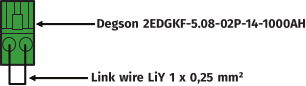
6.3.2 Adding power-cut circuit with E-STOP button
If specific SIL/PL rated level needs to be achieved, it might be necessary to install a power cut-off device. Two contactors connected in series and controlled by safety relay can be used to provide or cut-off power line to QS-SB2 power cabinets. When safety function on safety relay input is triggered, a safety relay will switch off the contactors, thus cutting-off the power to the platform. To apply this solution, Motion Lock Master or ML UP (depending on revision of the QS-SB2 power cabinet) connection cables needs to be replaced with prepared jumpers as described in section 6.3.1Info
To achieve required safety performance level it is necessary to perform safety risk assessment at customers site
Example application of power line contactors and E-STOP button:
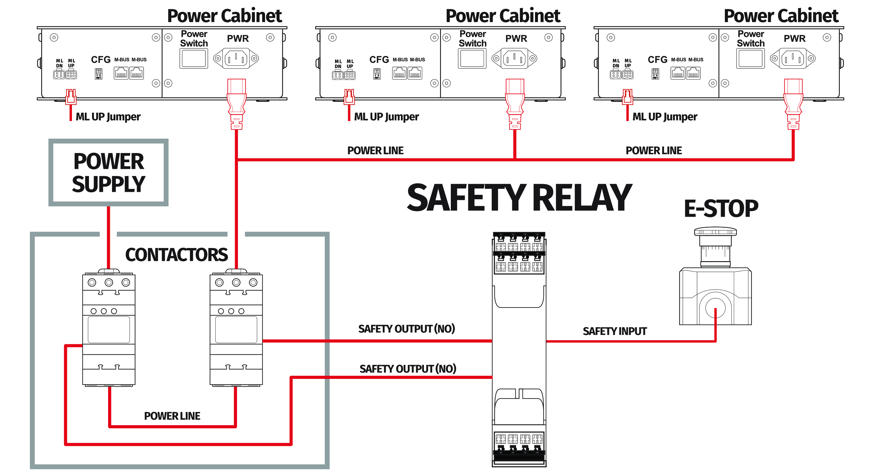
Example wiring diagram of application of power line contactors and E-STOP button:
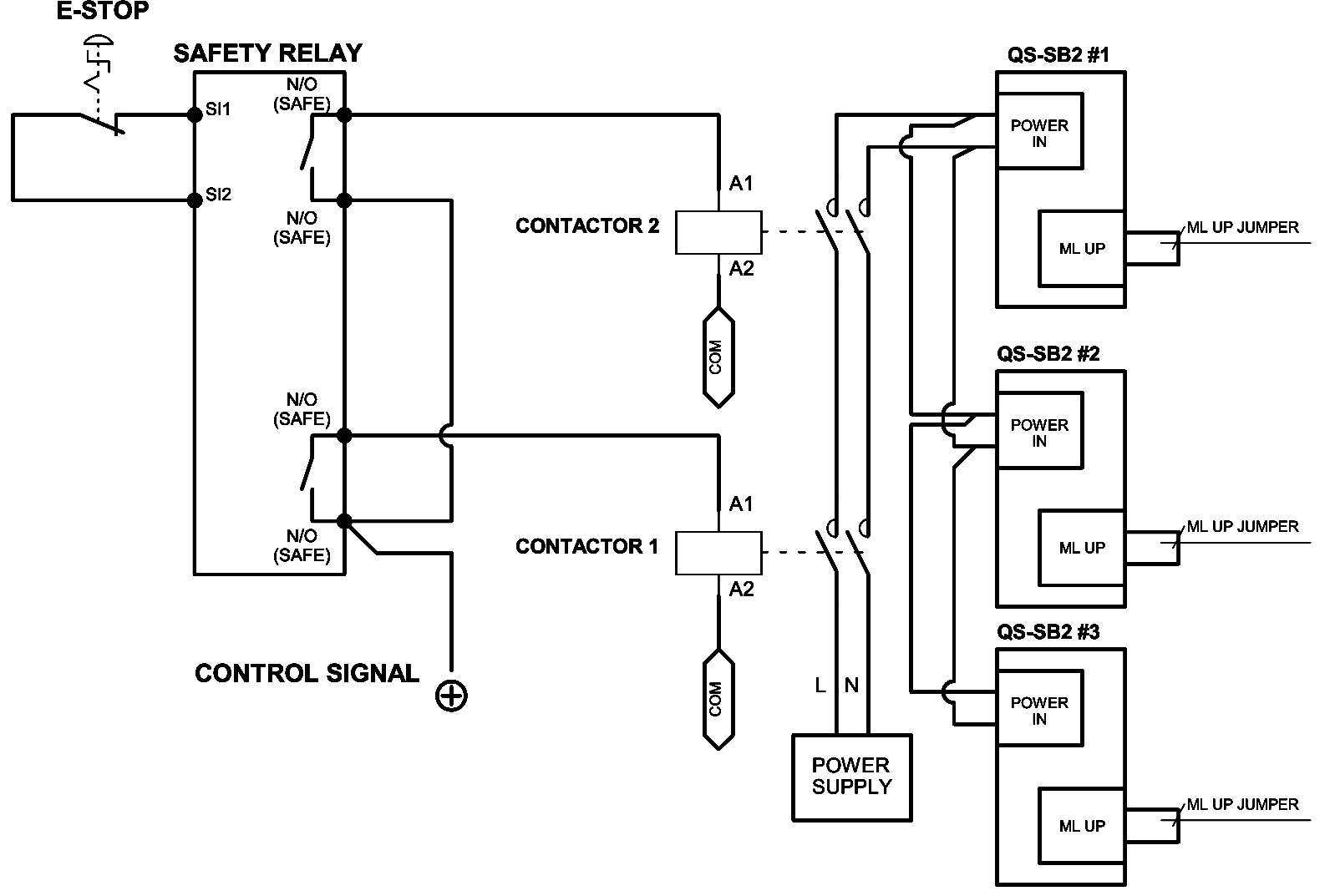
Info
PE (protective grounding/earthing) connection is omitted for better transparency
6.3.3 Implementing the working zone protection with power-cut circuit
In example application contactors connected in series provide power line to the QS-SB2 power cabinets. When safety function on safety relay input is triggered, a safety relay will switch off the power contactors, thus cutting-off the power to the platform.
Example application of power line contactors with safety gate opening sensor:
Info
When applying safety relay and contactors to the power line remember to:
- Use control cables according to your safety relay manual
- Power line cables shall be chosen accordingly to power requirements of motion system. See power requirements of specific motion system.
7 Conformity Information

The QS-220-PL meets the requirements of CE and relevant regulations of the EMC Directive 2014/30/EU and the RoHS Directive 2011/65/EU.
8 Environmental Impact and Disposal

Do not dispose of this product with standard household waste, drop it off at a collection point for the disposal of Waste Electrical and Electronic Equipment for recycling.
9 Liability Disclaimer
If permitted under applicable law, Motion Systems and its subsidiaries disclaim all liability for any damages caused by one or more of the following:- The product has been modified, opened, or altered.
- Failure to comply with a User Manual.
- Inappropriate or abusive use, negligence, an accident (an impact, for example).
- Normal wear.
Info
If permitted under applicable law, Motion Systems and its subsidiaries disclaim all liability for any damages unrelated to the material or manufacturing defect with respect to the product (including, but not limited to, any damages caused directly or indirectly by any software, or by combining the QS-220-PL with any unsuitable element or not other elements not supplied or not approved by Motion Systems for this product).
10 Warranty
Motion Systems warrants to the consumer that this product shall be free from defects in materials and workmanship, for a warranty period which corresponds to the time limit to bring an action for concerning this product. For commercial customers, there is a one (1) year limited warranty, starting on the original date of purchase. Within the warranty period, the product will be repaired or replaced free of charge, excluding shipping charges. This warranty shall not apply:- If the product has been modified, opened, altered, or has suffered damage as a result of inappropriate or abusive use, negligence, an accident, normal wear, or any other cause unrelated to a material or manufacturing defect (including, but not limited to, combining the QS-220-PL with any unsuitable element, including in particular power supplies, chargers, or any other elements not supplied or approved by Motion Systems for this product).
- In the event of failure to comply with the instructions provided by technical support.
- To software, said software being subject to a specific warranty.
- To accessories (cables, cases, for example).
- If the product was sold at public auction or if the product has suffered damage as a result of force majeure: flood, fire, earthquake, storm.
11 Copyright
Qubic System is a trademark of Motion Systems. All rights reserved. All the contents in this user manual are the intellectual property of Motion Systems. No part of this manual, including the products and software described in it, shall be modified or translated into any language without the prior written permission of Motion Systems. Specifications and information in this manual are subject to change at any time without obligation to notify any person of such revision or changes. Illustrations are not binding.Info
Trademark Notice - All brand names, icons, and trademarks that appeared in this manual are the sole property of their respective holders.
12 Manufacturer information
Motion Systems
Miedziana 7 Street
55-003 Nadolice Wielkie
Poland
Miedziana 7 Street
55-003 Nadolice Wielkie
Poland

Info
In support queries please contact your reseller.