Documentation Library
Qubic System — product manuals and technical documentation.
76 manuals
·
6 categories
Software
Software applications and simulation guides
Hardware
Motion platform hardware manuals
Tutorials
Step-by-step guides and tutorials
Product Cards
Product specification sheets and datasheets
Miscellaneous
Wallpapers and additional resources
3D Prints
3D printable models for motion platforms


QS-BT1
User manual for QS-BT1.
1 Introduction
QS-BT1 is a multi-purpose, dual-channel, direct-drive seat belt tensioner that increases the immersion of a racing simulator. It is powered by the same technology as QS-220 and provides force feedback similar to that offered by direct-drive wheels. QS-BT1 generates vibrations to simulate a running engine, tensions up with downshifts, upshifts, in corners, and finally - gives a strong pull when crashing. Importantly, it can also work as a standalone, fully independent device.
2 Safety precautions
Read all safety instructions before installing and using this product. Save this document for future reference. If ownership of this product is transferred, be sure to include this manual. Following coloured frames are used in this manual to draw attention to important information or warnings:Info
The instructions included in this frame indicate information that is considered important, but not injury- or damage-related.
Warning
The instructions included in this frame indicate a dangerous situation that, if not avoided, could result in a user injury or device damage.
2.1 General safety
Warning

DO NOT place hands, neck, or head under or wrap them around the belts.
Warning

Always ensure that cockpit attachment points can withstand forces generated by the device (approved construction or tested for expected load). The maximum force generated by the QS-BT1 is 200 N on each belt.
Warning

Keep in mind that dangerous voltage levels can remain in electrical circuits of the device for up to a few minutes after powering off.
Warning

The device is intended solely for individuals OVER THE AGE OF 16. In case of use by individuals with limited physical, sensory, or mental capabilities, strict supervision is required. Read safety instructions before using the device.
Warning

The device is NOT allowed to be used by a pregnant woman.
Warning

DO NOT use the device around pets.
- Use the QS-BT1 only for its intended purpose, according to instructions.
- Unplug the QS-BT1 from the power supply if it is not used for an extended period of time or when there is a need to perform hardware installation, maintenance, service or repair.
- Turn off the QS-BT1 when it is not in use.
- The QS-BT1 was designed for indoor use only - DO NOT store or use the product outdoors.
- Keep the QS-BT1 away from heat sources, high humidity, water, and other liquids. DO NOT store in places where water vapor condensation may occur due to low temperatures.
- DO NOT disassemble the product. Any tampering with or altering the product will void the warranty, pose a serious risk of electric shock, and may irreparably damage the product.
- If the device starts emitting unusual noises, smoke, or indicating that the device is not working properly, STOP using the QS-BT1 immediately and contact technical support.
- DO NOT cover the ventilation holes in the device.
- Keep the power cord plug and the socket dry, clean and dust-free.
- Protect the power cord from being damaged by being stepped on, rubbed against, or pinched.
- DO NOT use the QS-BT1 if the ambient temperature is below 5°C (41°F) or above 40°C (104°F).
- DO NOT use the QS-BT1 if it has been damaged, or any component is broken or missing. Please contact technical support.
- DO NOT use attachments or replacement parts not recommended or approved by the manufacturer. If you must replace a damaged power cord, use only certified products with the same rating as the one being replaced.
- Before each use of the device ensure that it is securely mounted to the motion rig.
- Before each use of the device ensure that belt buckles are securely mounted to the harness.
- Use only certified components (seat belts, fasteners) when installing QS-BT1 to your motion rig.
- QS-BT1 's buckles are compatible with 2- and 3-inch harnesses.
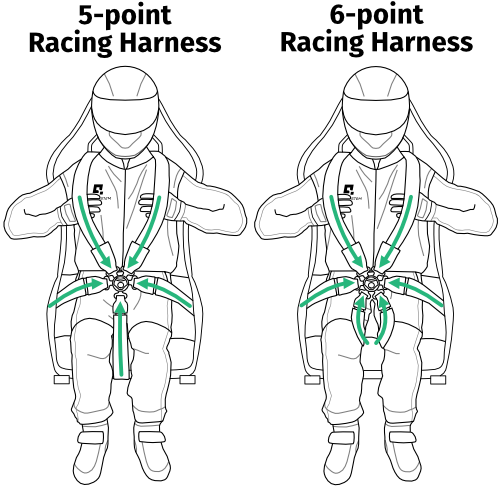
- Use 5 or 6-point racing harness, with adjusters (look at point A in the drawing below), preferably with FIA certification.
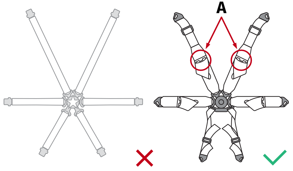
Warning
As with a racing harness, the QS-BT1 seatbelts are subject to significant forces. FIA-certified belts feature much higher strength in both the webbing and the buckle. Low-cost sim racing belts are not designed to withstand real forces: the buckle may fail during simulation, and the belts could spring upward with considerable force, potentially striking the user's face.
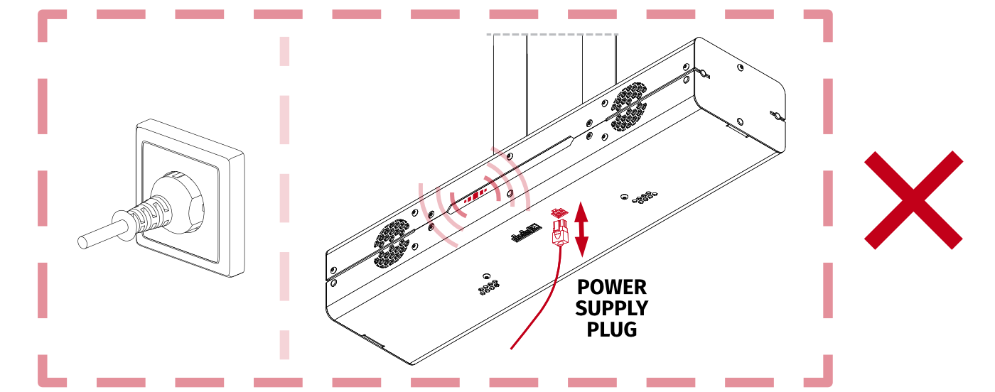
Info
NEVER disconnect or connect the Power Supply plug to the QS-BT1 with Power ON. For details - go to section 4.9.1.
3 Technical details
3.1 Intended use
The device is intended to work as a INDOOR seat belt tensioner for vehicle and flight simulations. It is not classified as a safety device and can be used ONLY for entertainment and training purposes.Warning
It is forbidden to use the device in applications other than intended.
3.2 List of components
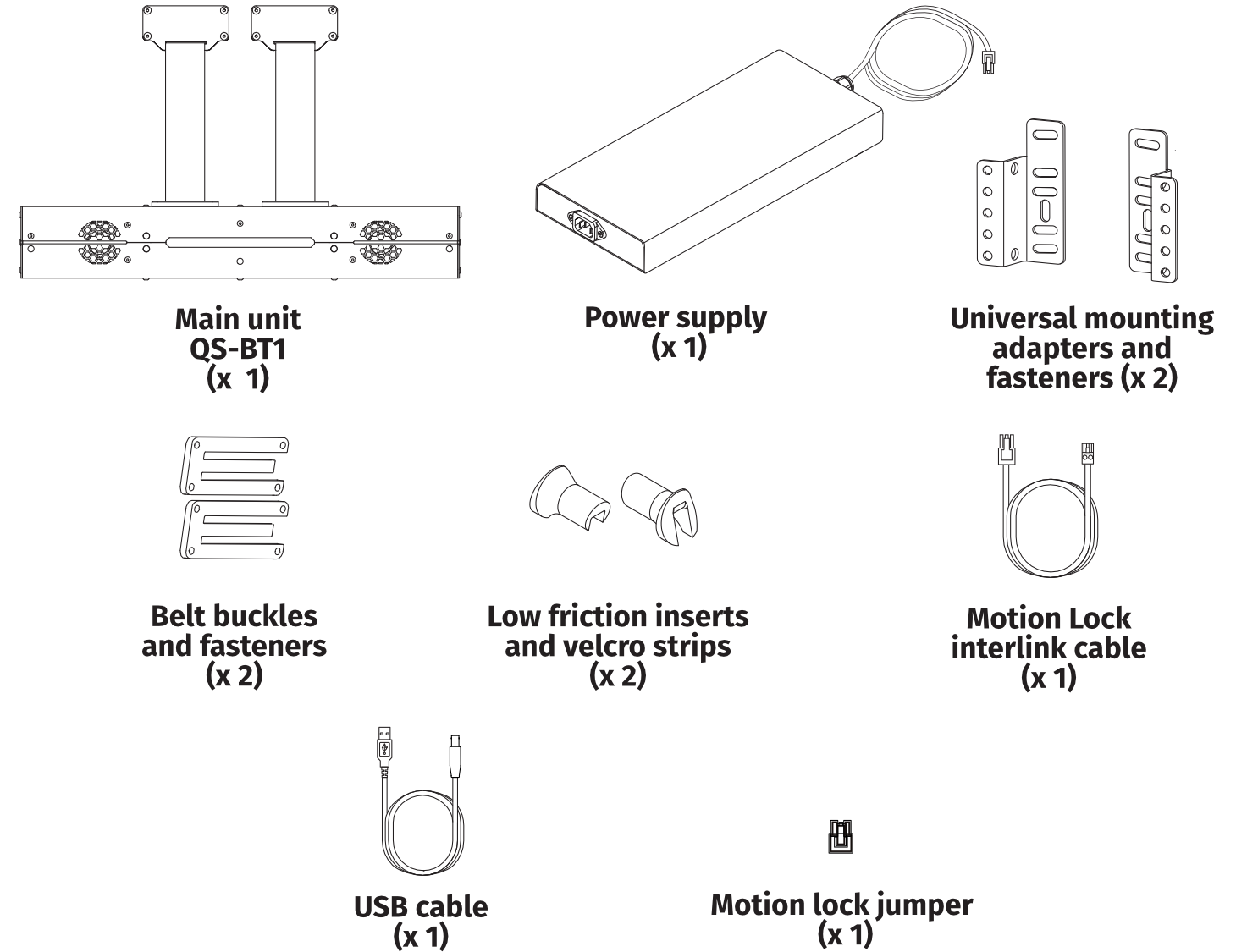
Info
The QS-BT1 package does not include racing harness; user needs to obtain it separately.
3.2.1 Power Cord
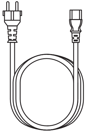
The power cord for QS-BT1 is provided as a separate component and is selected based on the electrical standards and socket types applicable in the target market. This ensures compatibility with regional voltage, frequency, and plug configurations.
3.3 Operating and storage conditions
QS-BT1 should be operated and stored within conditions as specified below:- Only indoor use and storage
- Temperature: 5°C - 40°C (41°F - 104°F)
- Humidity: 0% - 70% (without water vapor condensation)
- Maximum altitude: 0 - 2000 m (6561 ft)
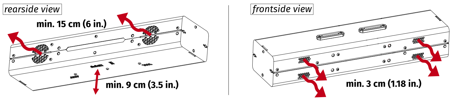
- Ensure a correct distance from QS-BT1 's cooling vents on the backside (min. 15 cm / 6 in.) and on the frontside (min. 3 cm / 1.18 in.). Ensure min. 9 cm (3.5 in.) for cable plugs underneath - more details on mounting solution in section 4.2.1.
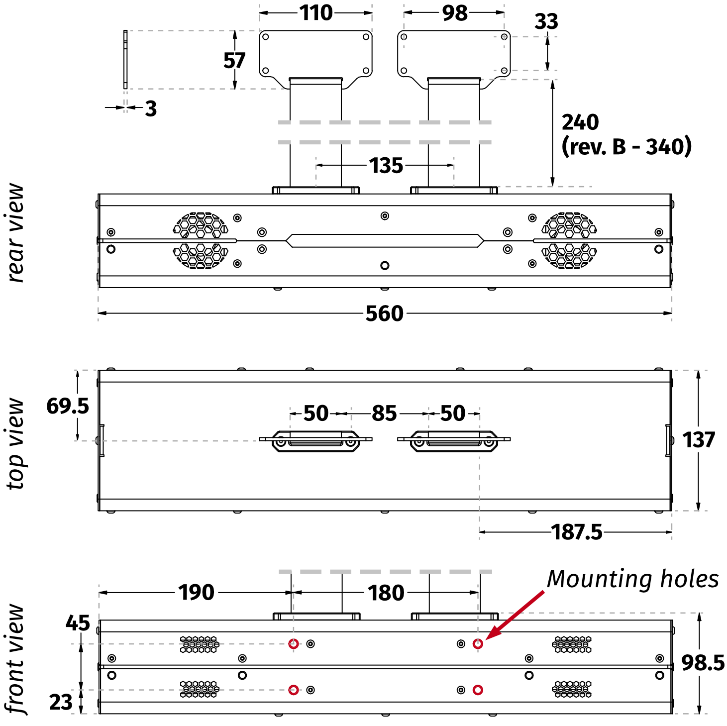
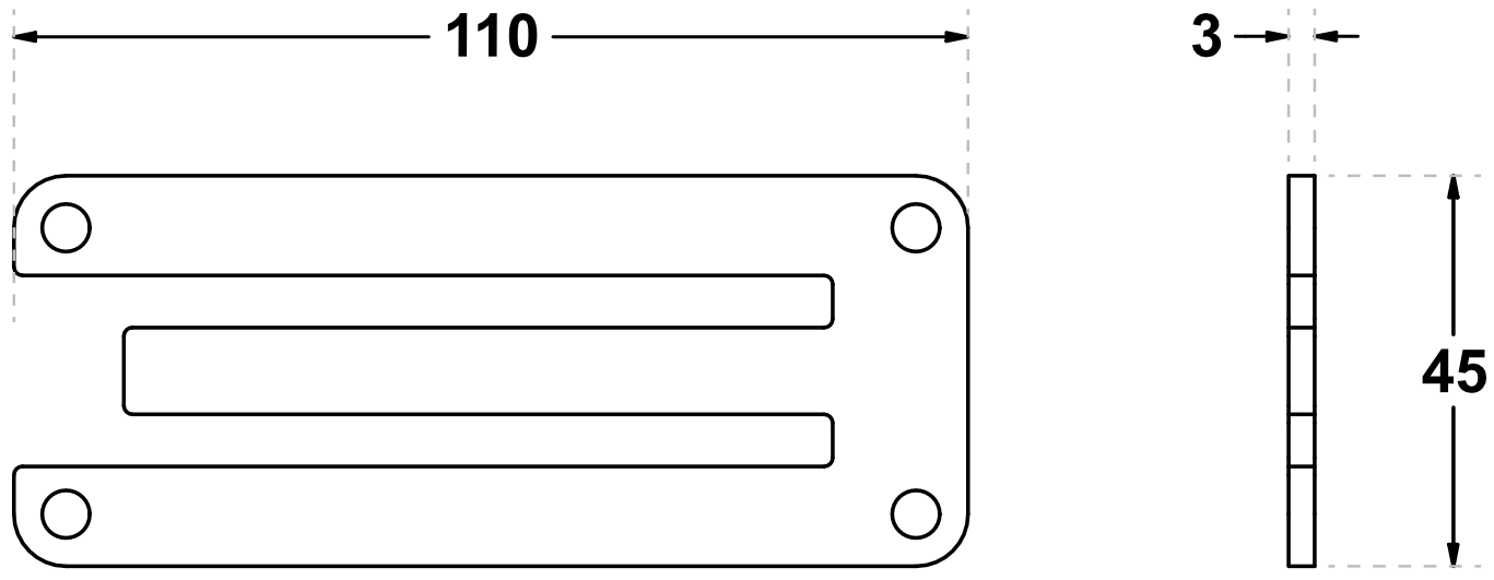
3.4 Dimensions and weight
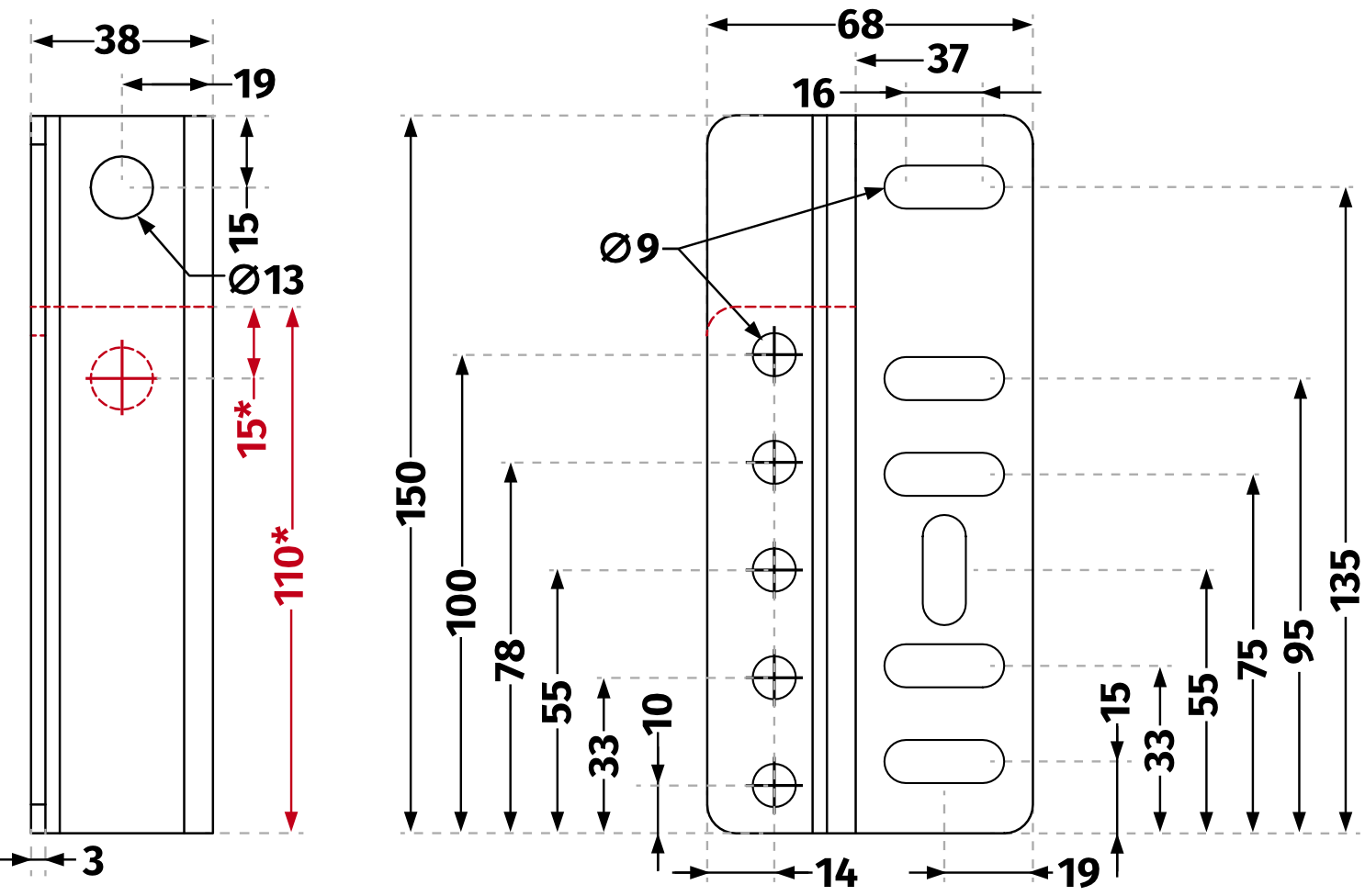
UNIVERSAL MOUNTING ADAPTER DIMENSIONS
SEAT INSERTS DIMENSIONS
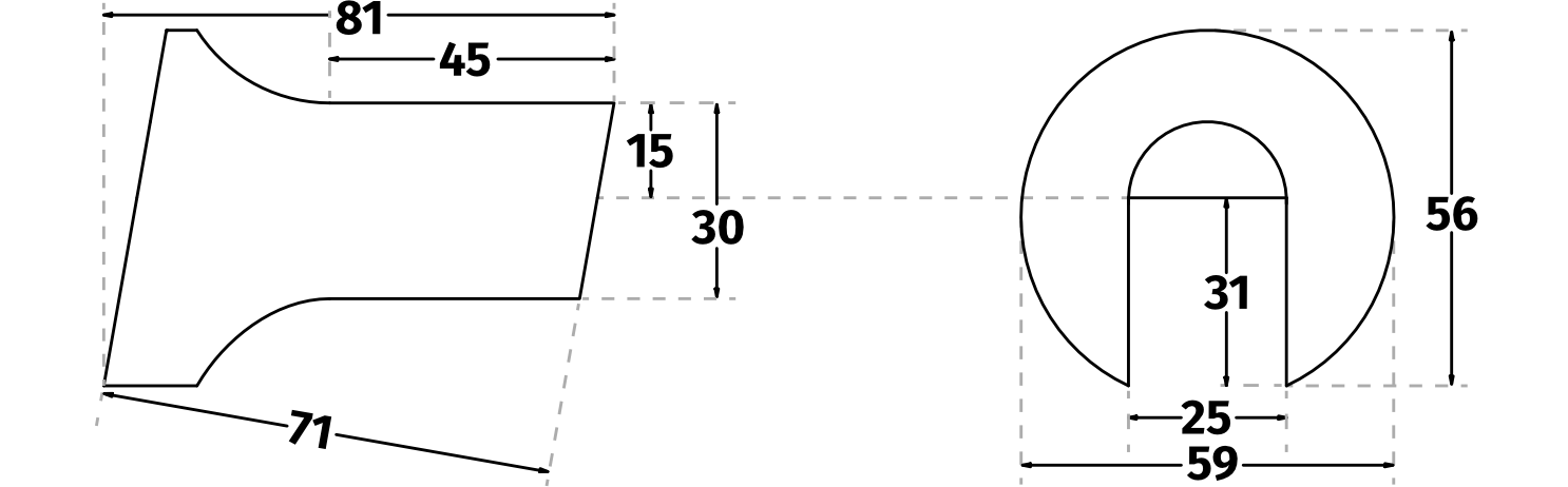
BELT BUCKLE DIMENSIONS
QS-BT1 'S WEIGHT
The QS-BT1 unit's weight is: 13 kg (28.66 lbs) [without cockpit mounting adapters].
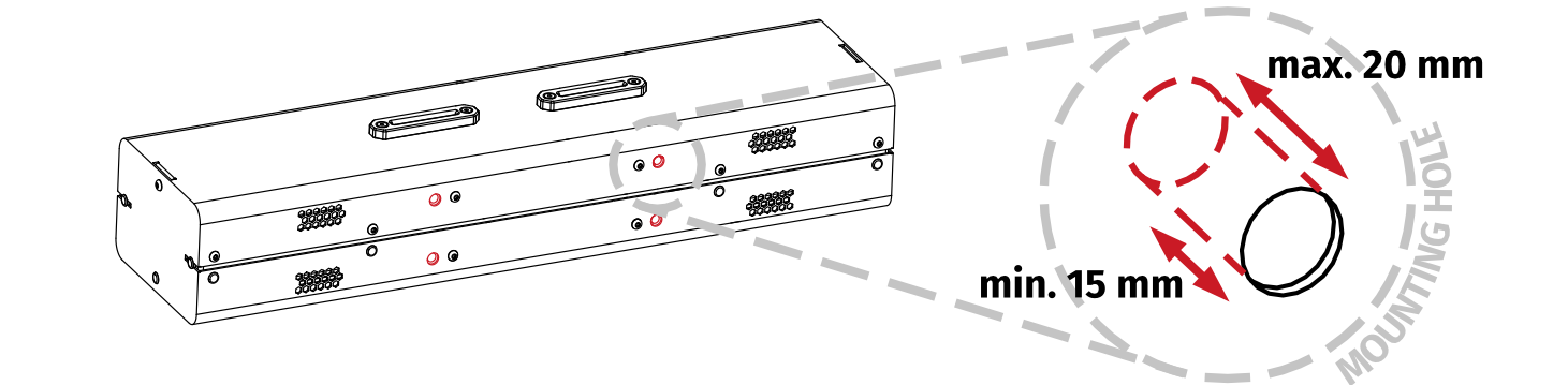
MOUNTING HOLE DIMENSIONS
Ensure at least 15 mm of thread engagement. Do not exceed 20 mm insertion depth.
INCLUDED CABLES LENGTHS
- Power supply's integrated cable - 1.9 m (75 in.)
- Power cord for power supply - 1.8 m (71 in.)
- USB cable - 3 m (118 in.)
- Motion lock interlink cable - 2 m (79 in.)
3.5 Power requirements
QS-BT1 requires a 120/230± 10% VAC 50-60 Hz single phase with ground and neutral connection.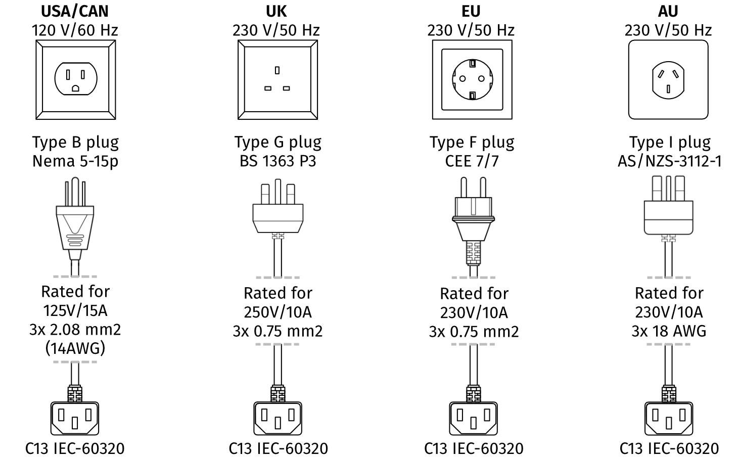
Info
Always UNWIND THE CABLE COMPLETELY when using a cable reel and untangle an extension cord before connecting the device to the power supply.

Warning
- The device is NOT intended to be used in an IT earthing/grounding system.
- The product must be connected to the mains power supply with a protective earth (PE) and a residual current circuit breaker (RCCB).
- Device MUST NOT be powered from an electrical circuit with a floating protective earth (PE) (floating PE - no grounding pin in the socket or grounding pin not connected with grounding circuit). In case of damage to the device caused by the lack of proper grounding - the warranty will be void.
3.6 Power consumption
Power Supply Unit contains the power supply for the QS-BT1 and it requires between 100 and 240 of input Voltage and operates at 480 Watts of maximum power. If there is no certainty if fuses or entire electrical installation can handle QS-BT1 , contact a qualified electrician.| Input | |
|---|---|
| Voltage range | 100-240VAC |
| Frequency range | 50-60Hz |
| Current | 7.0A max |
| Output | |
| Voltage (DC) | 24V |
| Max Current | 20A |
| Max Power | 480W |
| Ripple and noise | ≤300mV |
3.7 Noise emission
The QS-BT1 was checked for noise level emission. Noise level during normal work conditions is not over 50 dB. Measurements method complies with ISO 11202 standard. Four measuring positions as shown on the picture are placed 160 cm from the floor level and 100 cm from the edge of the device.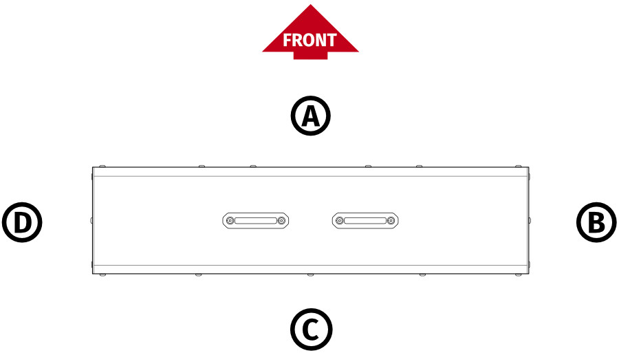
| Measurement point | A | B | C | D |
|---|---|---|---|---|
Measurement conditions:
| 44,6 dB | 47 dB | 48 dB | 42 dB |
4 Setup and installation
4.1 Pre-installation guidelines
During the installation follow specific guidelines for your safety, device duration and installation efficiency:- Make sure you are equipped with torque wrench and follow the torque specs for each bolt:
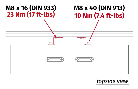
No. Part description Torque in Nm Torque in ft-lbs 1 DIN 913 M8 bolt 10 Nm 7.4 ft-lbs 2 DIN 933 M8 bolt 23 Nm 17 ft-lbs 3 DIN 912 M8 bolt 23 Nm 17 ft-lbs 4 ISO 7380-1 M5 bolt 4 Nm 3 ft-lbs - Use mild thread locker on every bolt that is not screwed in with a locknut.
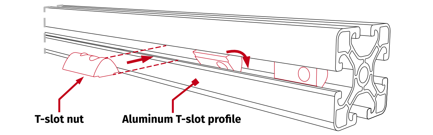
- Keep in mind, that T-slot nuts can be inserted in any given part of the aluminum profile, not only from open ends:
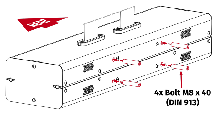
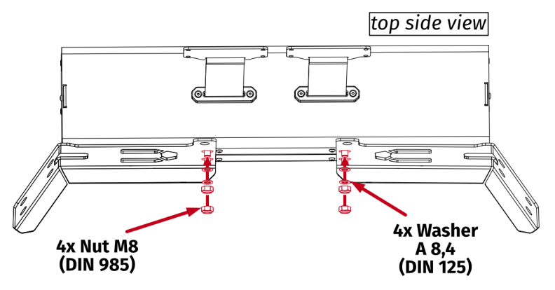
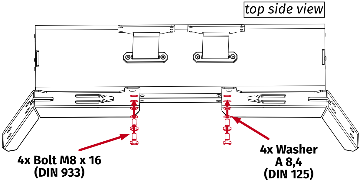
4.2 Attaching to the aluminum based cockpit profile
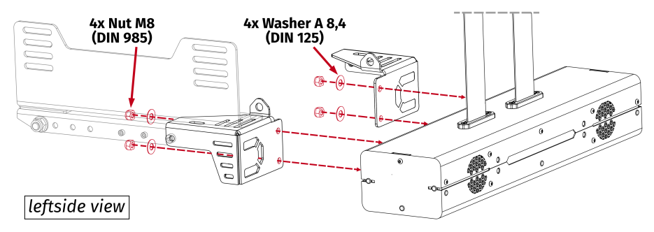
If you have a custom cockpit based on aluminum profiles, QS-BT1 must be mounted using universal mounting adapters.
Assembly parts included with QS-BT1 :
| No. | Part description | Qty. |
|---|---|---|
| 1 | Universal mounting adapter | 2 |
| 2 | T-slot nut M8 | 4 |
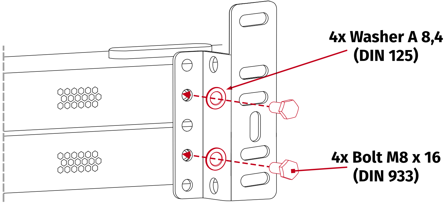
| 3 | Bolt M8 x 16 (DIN 933) | 4 |
| 4 | Washer A8,4 (DIN 125) | 8 |
| 5 | Bolt M8 x 40 (DIN 913) | 4 |
| 6 | Nut M8 (DIN 985) | 4 |
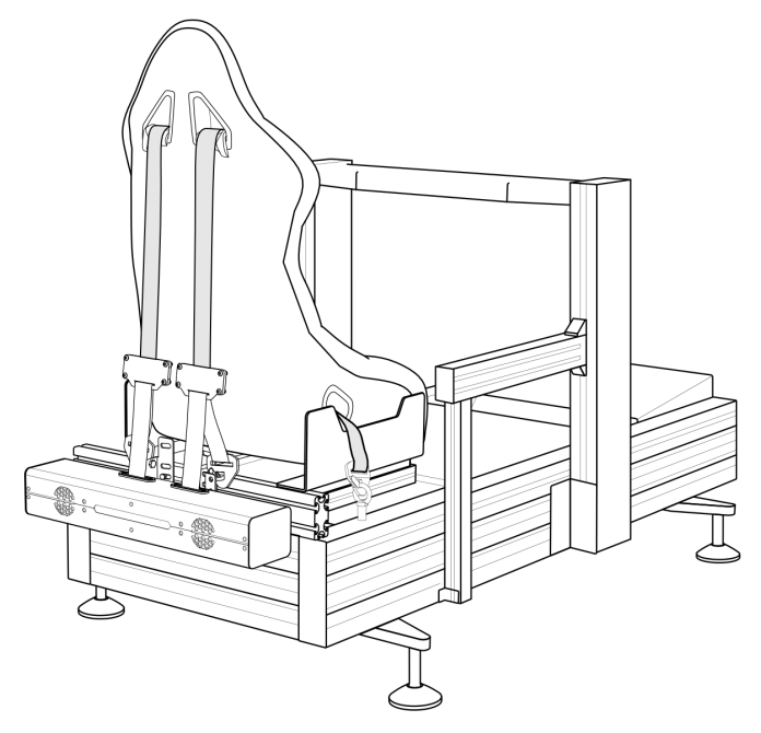
Info
Illustration of a finished assembly with a sample aluminum based cockpit profile.
Warning
- Ensure that your cockpit construction and attachment points can withstand forces generated by the device. The maximum generated force is 200 N on each belt.
- In case of motion platform implemented cockpits - the QS-BT1 always MUST BE mounted to a position that is moving along with the seat.
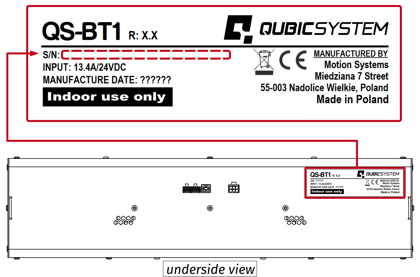
Info
Before installing the QS-BT1 to a cockpit - write down Serial Number which is located on the underside of the device. Refer to section 5.2 for details. Serial Number is also available on the side of packaging box.
Info

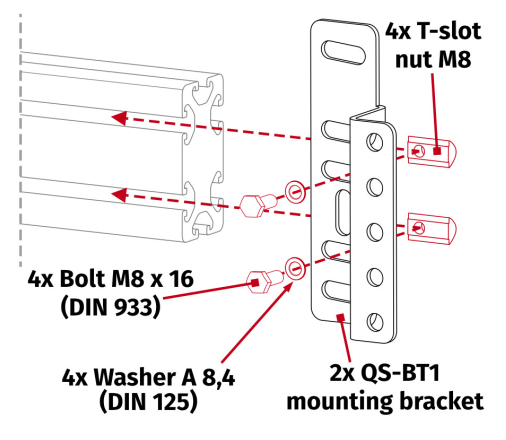
Previous revisions include mounting brackets of a different shape but the mounting solution remains the same.
- Slide the T-Slot nuts (they can also be inserted directly into the T-slot nut channel at any spot) into the cockpit rear profile bar and then screw in the universal adapter using bolts and washers by hand. Do not torque down the bolts yet.
- Adjust the space between mounting brackets to match the belt tensioner mounting holes.
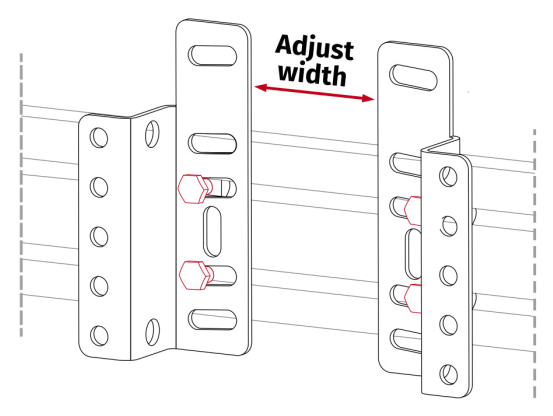
- Screw in included bolts into the QS-BT1 (hex key for DIN 913 bolts is not included). Do not overtorque them - maximum 10 Nm (7.4 ft-lbs) of torque.

- Attach the QS-BT1 to mounting brackets.
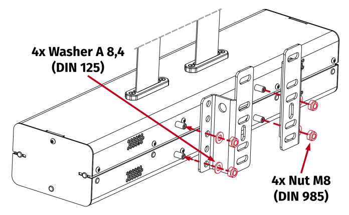
- Torque down bolts and nuts.
Warning
A device running with incorrectly tightened bolts is dangerous to a user and will cause irreversible damage to the hardware and mounting points.
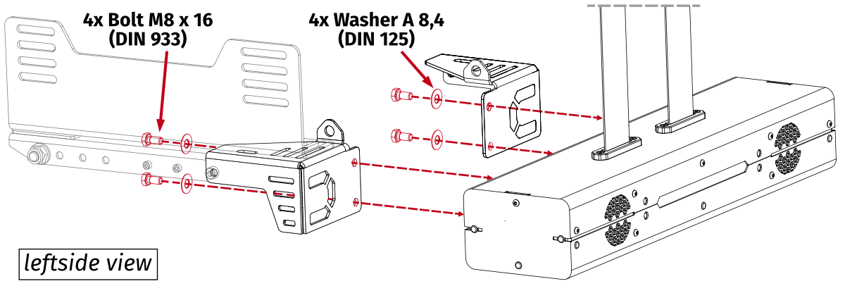
Info
Revision B of QS-BT1 is using different mounting hardware:
4.2.1 Alternative mounting for cable clearance
If a default mounting solution does not provide a minimum of 9 cm (3.5 in.) of cable clearance underneath the QS-BT1 - there is a alternative mounting solution using the same mounting adapters. Flip the mounting adapters upside-down and use different mounting holes, as in the picture below: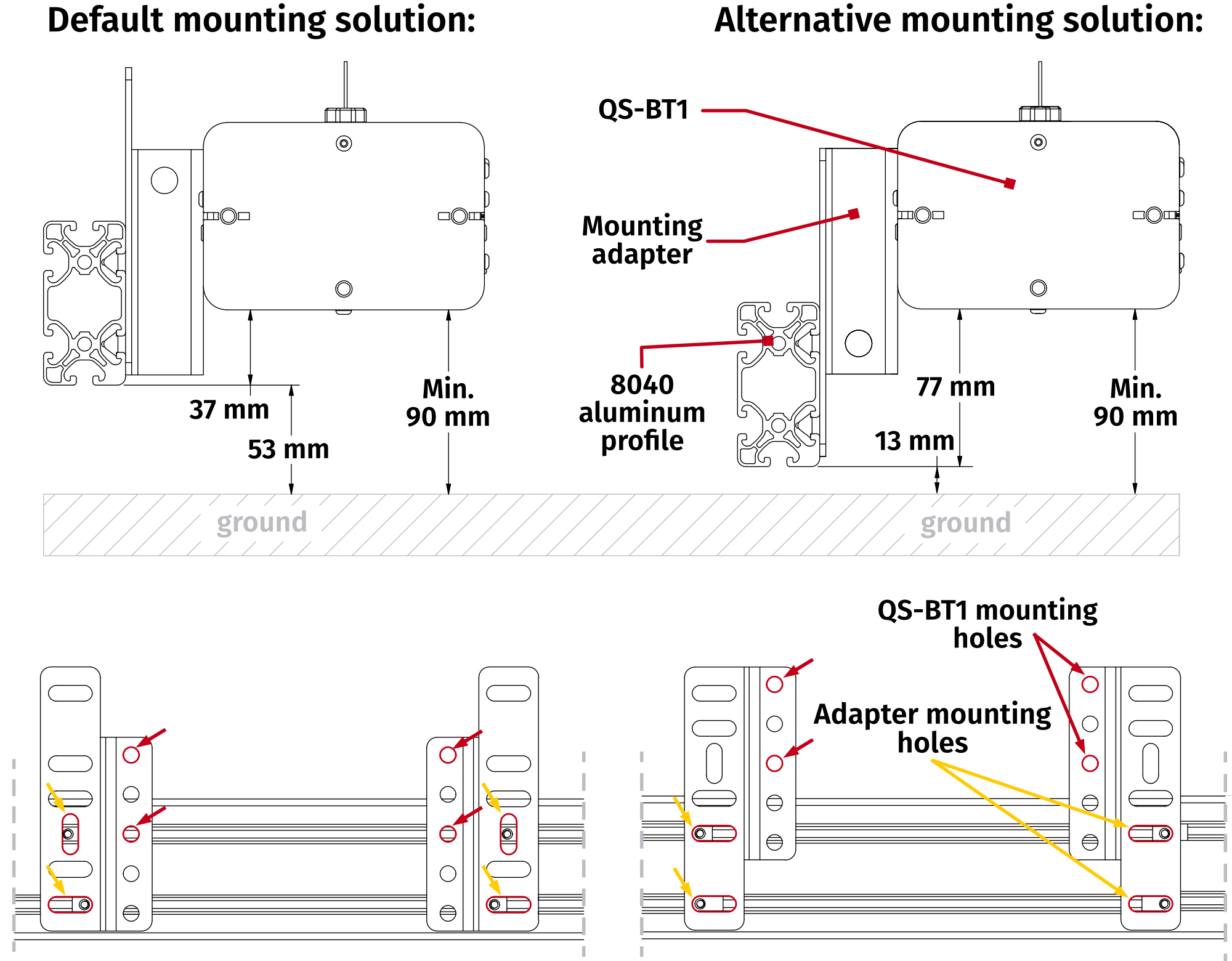
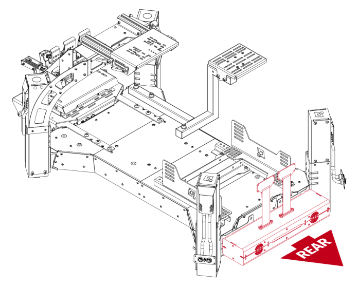
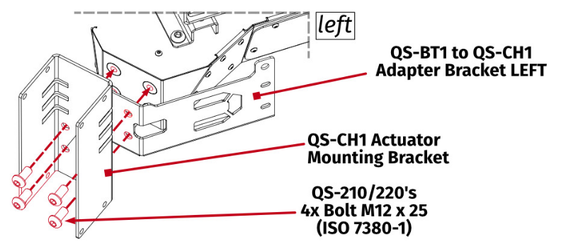
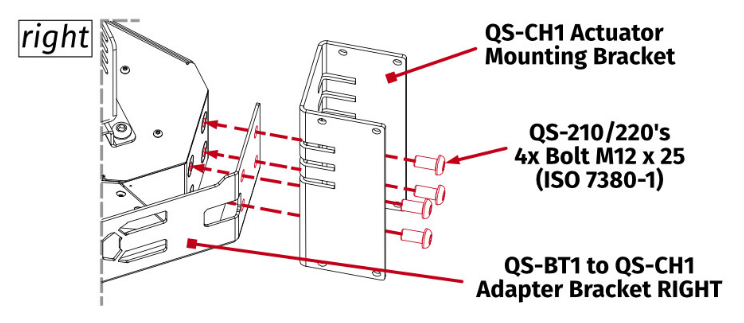
4.3 Attaching to QS-CH1
The QS-BT1 should be attached to QS-CH1 using two mounting brackets (not included - can be purchased separately from our retailers).
Assembly parts included with QS-BT1 :
| No. | Part description | Qty. |
|---|---|---|
| 1 | Bolt M8 x 40 (DIN 913) | 4 |
| 2 | Nut M8 (DIN 985) | 4 |
| 3 | Washer A8,4 (DIN 125) | 4 |
Assembly parts included with QS-CH1 mounting brackets:
| No. | Part description | Qty. |
|---|---|---|
| 1 | Mounting brackets | 2 |
Info
Illustration of a finished assembly.
Info
Before installing the QS-BT1 to a cockpit - write down Serial Number which is located on the underside of the device. Refer to section 5.2 for details. Serial Number is also available on the side of packaging box.
Info
Mounting brackets are NOT interchangeable. Metal lip must be at the bottom.
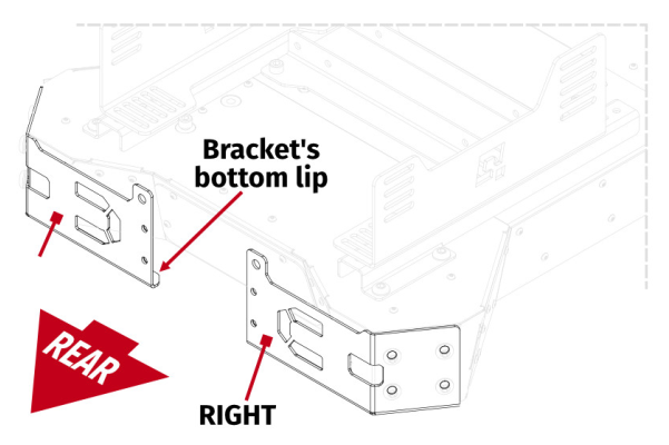
- Unscrew QS-210/220's back actuators. Attach the QS-BT1 mounting bracket between the device's base and the actuator mounting bracket. Tighten all QS-210/220's four bolts to 25 Nm (18.5 ft-lbs) of torque.
- Repeat the operation on the other side.
- Screw in included bolts into the QS-BT1 (hex key for DIN 913 bolts is not included). Do not overtorque them - maximum 10 Nm (7.4 ft-lbs) of torque.
- Attach the QS-BT1 to mounting brackets.
- Attach the actuators back to their brackets. For details, refer to QS-CH1 user manual.
Info
Revision B of QS-BT1 is using different mounting hardware:
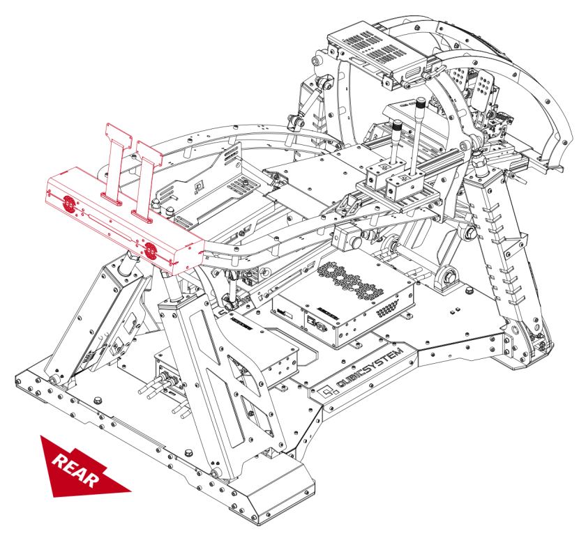
4.4 Attaching to QS-V20
The QS-BT1 should be attached to QS-V20 using a mounting bracket (not included - can be purchased separately from our retailers).
Assembly parts included with QS-BT1 :
| No. | Part description | Qty. |
|---|---|---|
| 1 | Bolt M8 x 40 (DIN 913) | 4 |
| 2 | Nut M8 (DIN 985) | 4 |
| 3 | Washer A8,4 (DIN 125) | 4 |
Assembly parts included with QS-V20 mounting bracket:
| No. | Part description | Qty. |
|---|---|---|
| 1 | Mounting bracket | 1 |
| 2 | Bolt M8 x 25 (DIN 912) | 4 |
| 3 | Nut M8 (DIN 985) | 2 |
| 4 | Washer A 8,4 (DIN 125) | 2 |
Info
Illustration of a finished assembly.
Info
Before installing the QS-BT1 to a cockpit - write down the Serial Number which is located on the underside of the device. Refer to section 5.2 for details. Serial Number is also available on the side of packaging box.
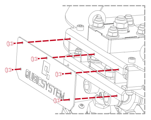
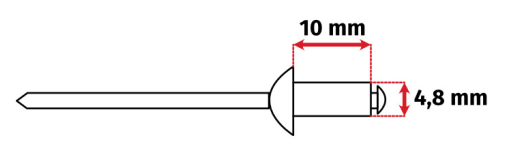
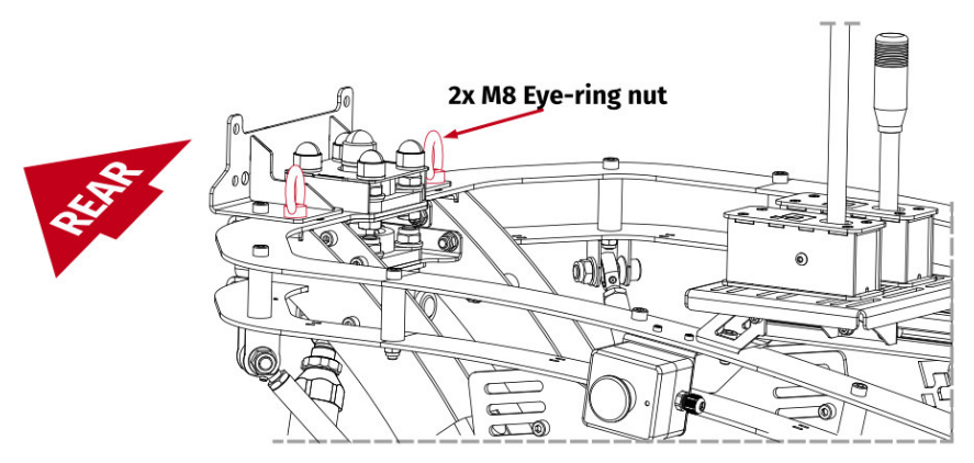
- OPTIONAL for easier access - unscrew the rear logo plate (in case of rivets using assembly - drill them out).
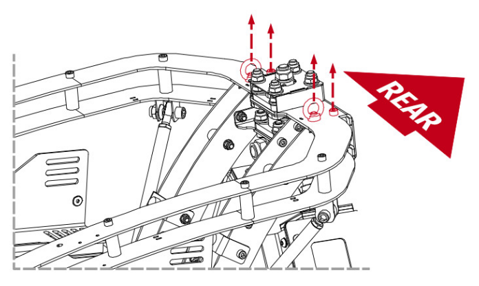
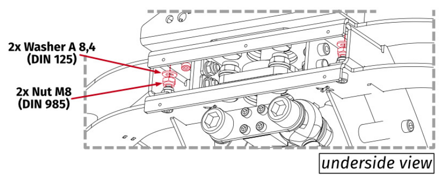
- Unscrew the bolts and eye-ring nuts from the QS-V20's frame.
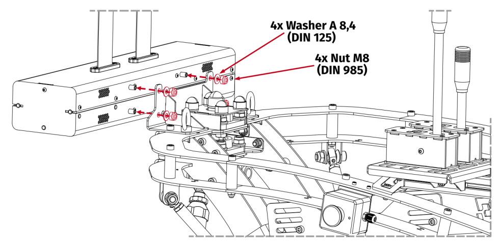
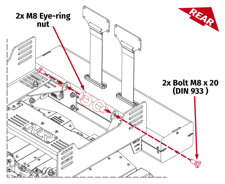
- Rest the bracket flat on the QS-V20 frame and put through back mounting bolts from the top. Screw on eye-ring nuts on the front bolts that were inserted from the bottom.
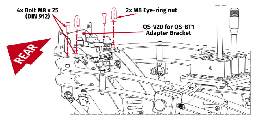
- Screw nuts on the back bolts from underneath. Torque down all four bolts to 23 Nm (17 ft-lbs) of torque while holding two nuts from underneath with a flat wrench and eye-rings from the top.
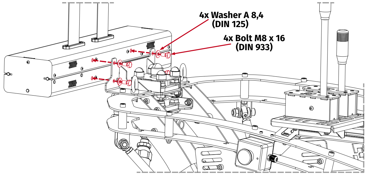
- Screw in included bolts into the QS-BT1 (hex key for DIN 913 bolts is not included). Do not overtorque them - maximum 10 Nm (7.4 ft-lbs) of torque.

- Attach the QS-BT1 to mounting brackets.
- OPTIONAL - mount the logo plate back on. In case of rivets using assembly use a rivet gun with 4.8 mm x 10 mm blind rivets.
Info
Revision B of QS-BT1 is using different mounting hardware:
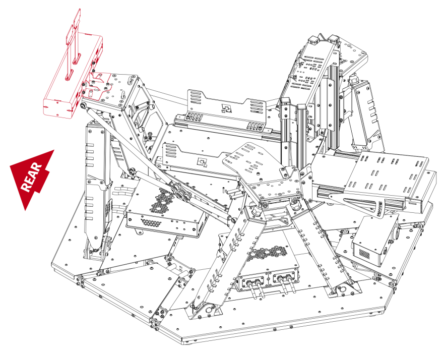
4.5 Attaching to QS-S25
The QS-BT1 should be attached to the QS-S25 using a mounting bracket (not included - can be purchased separately from our retailers).
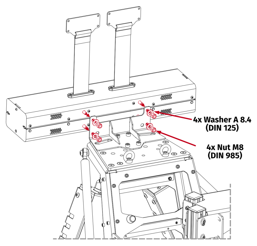
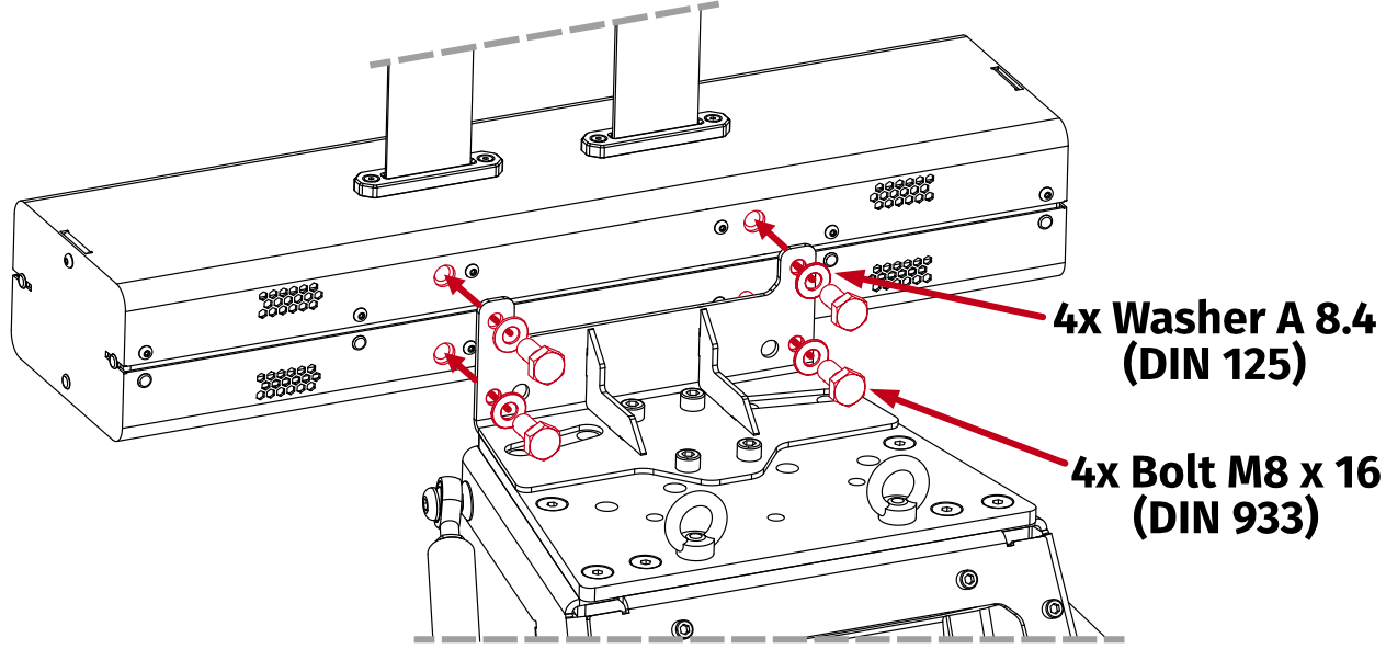
Assembly parts included with QS-BT1 :
| No. | Part description | Qty. |
|---|---|---|
| 1 | Bolt M8 x 40 (DIN 913) | 4 |
| 2 | Nut M8 (DIN 985) | 4 |
| 3 | Washer A8,4 (DIN 125) | 4 |
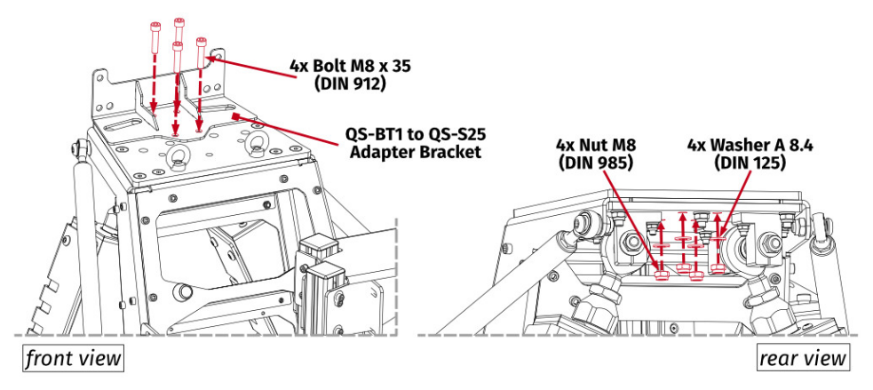
Assembly parts included with QS-S25 mounting bracket:
| No. | Part description | Qty. |
|---|---|---|
| 1 | Mounting bracket | 1 |
| 2 | Bolt M8 x 35 (DIN 912) | 4 |
| 3 | Nut M8 (DIN 985) | 4 |
| 4 | Washer A 8,4 (DIN 125) | 4 |
Info
Illustration of a finished assembly.
Info
Before installing the QS-BT1 to a cockpit - write down Serial Number which is located on the underside of the device. Refer to section 5.2 for details. Serial Number is also available on the side of packaging box.
- Attach the QS-BT1 bracket to the back of QS-S25 frame. Rest the bracket flat on the QS-S25 frame and put through mounting bolts. Screw in the nuts on the bolts from underneath. Torque down all four bolts to 23 Nm (17 ft-lbs) of torque while holding the nuts from underneath with a flat wrench.
- Screw in included bolts into the QS-BT1 (hex key for DIN 913 bolts is not included). Do not overtorque them - maximum 10 Nm (7.4 ft-lbs) of torque.

- Attach the QS-BT1 to mounting brackets.
Info
Revision B of QS-BT1 is using different mounting hardware:
4.6 Attaching to Next Level Racing Motion Platform V3
Warning
- sep-0.3em
- DO NOT attach QS-BT1 to the platform cockpit. Belt tensioner MUST be attached to a mobile top frame of the NLR Motion Platform V3 unit.
- You CANNOT use QS-BT1 with standard Buttkicker Gamer 2 bracket.
- Adding QS-BT1 reduces maximum user weight for NLR Motion Platform V3 down to 115 kg (253 lbs).
Assembly parts included with QS-BT1 :
| No. | Part description | Qty. |
|---|---|---|
| 1 | Bolt M8 x 40 (DIN 913) | 4 |
| 2 | Nut M8 (DIN 985) | 4 |
| 3 | Washer A8,4 (DIN 125) | 4 |
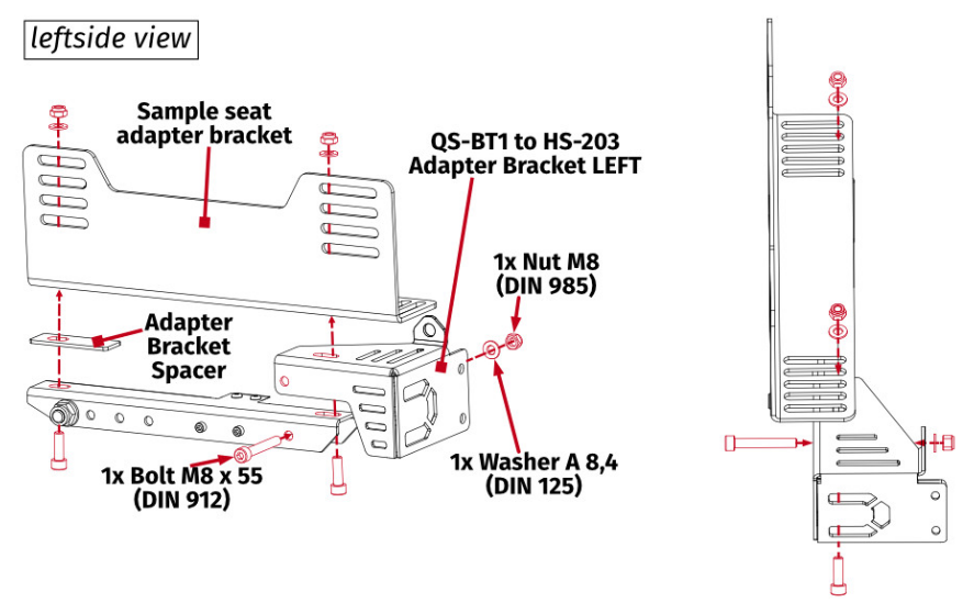
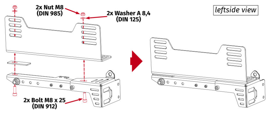
Assembly parts included with NLR Motion Platform V3 mounting bracket:
| No. | Part description | Qty. |
|---|---|---|
| 1 | Mounting bracket | 2 |
| 2 | Spacer | 2 |
| 3 | Bolt M8 x 55 (DIN 912) | 2 |
| 4 | Nut M8 (DIN 985) | 6 |
| 5 | Washer A 8,4 (DIN 125) | 6 |
| 6 | Bolt M8 x 25 (DIN 912) | 4 |
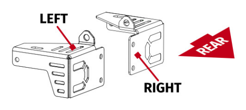
Info
Adapting brackets are not interchangeable. Refer to illustration below.
Info
Before installing the QS-BT1 to a cockpit - write down Serial Number which is located on the underside of the device. Refer to section 5.2 for details. Serial Number is also available on the side of packaging box.
Info
Illustration of a finished assembly with a sample cockpit.
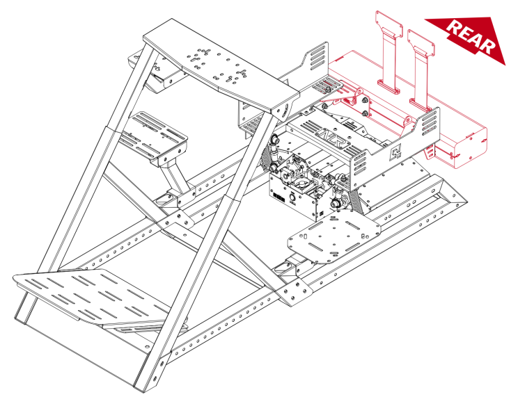
- Remove the seat from seat adapter bracket.
- Attach the QS-BT1 mounting bracket and spacer between the top frame of the NLR Motion Platform V3 motion unit and the seat mounting bracket.
InfoThe seat adapter bracket in the illustrations below serves only as an example. The QS-BT1 's adapter brackets must be attached to your seat adapter/seat rails.
- Attach the seat mounting bracket to the top frame of NLR Motion Platform V3 motion unit. Tighten the bolts to 23 Nm (17 ft-lbs) of torque while holding the nuts with a flat wrench.
- Screw in included bolts into the QS-BT1 (hex key for DIN 913 bolts is not included). Do not overtorque them - maximum 10 Nm (7.4 ft-lbs) of torque.

- Attach the QS-BT1 to mounting brackets.
Info
Revision B of QS-BT1 is using different mounting hardware:
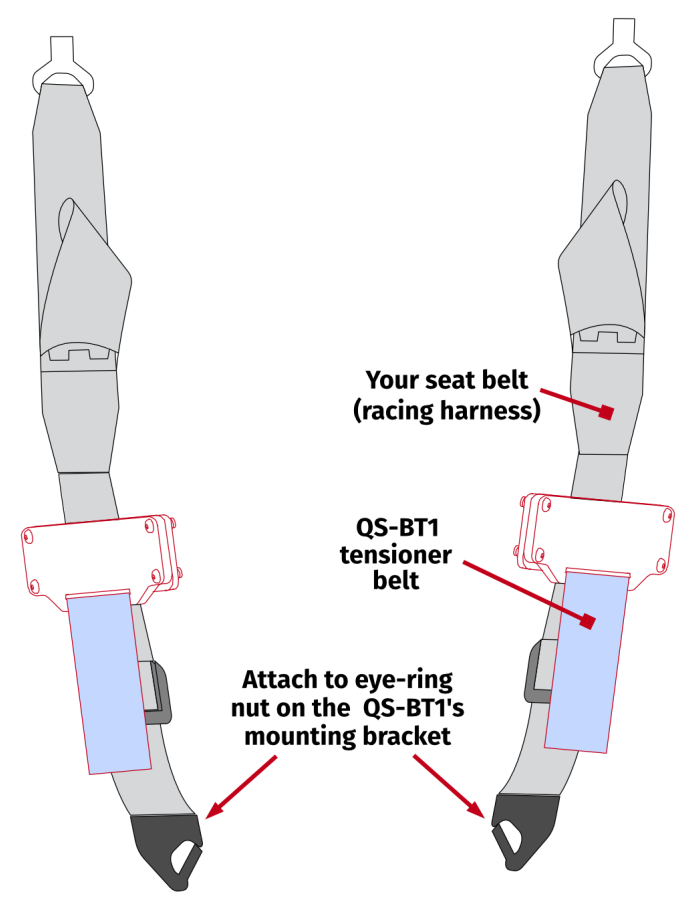
4.7 Belt installation
QS-BT1 's buckles are compatible with 2- and 3-inch harnesses.4.7.1 Attaching harness to the platform
Info
- Attaching harness to the platform (with snap-hooks or a shackle) is highly recommended. The QS-BT1 should only work as a belt tensioner, not a belt's hooking point.
- First - attach the harness to a cockpit and adjust it for the user (section 4.8.1), second - attach tensioner buckles to the harness.
Warning
All operations MUST be performed with the power OFF.
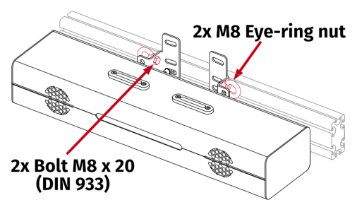
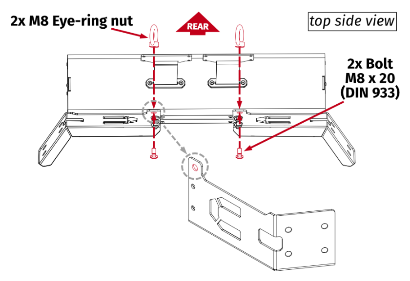
- Universal adapter bracket
Mount eye-ring nuts to the QS-BT1 's mounting bracket (hardware not included). Then attach the seat belt's snap hooks to the eye-ring nuts.
- QS-CH1
Mount eye-ring nuts to the QS-BT1 's mounting bracket (hardware not included). Then attach the seat belt's snap hooks to the eye-ring nuts.
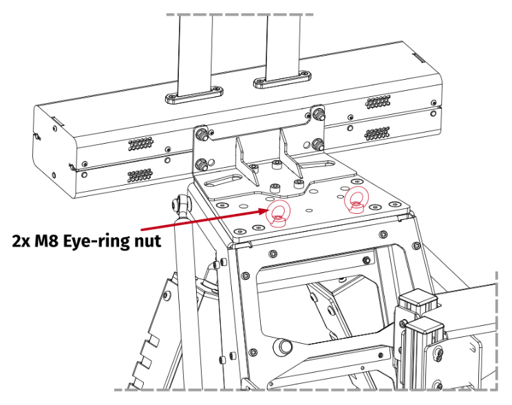
- QS-V20
Attach the seat belt's snap hooks to the eye-ring nuts. Eye-ring nuts are equipped from factory.
- QS-S25
Attach the seat belt's snap hooks to the eye-ring nuts. Eye-ring nuts are equipped from factory.
- Next Level Racing Motion Platform V3
Mount eye-ring nuts to the QS-BT1 's mounting bracket (hardware not included). Then attach the seat belt's snap hooks to the eye-ring nuts.
4.8 Seat belt settings
4.8.1 Seat belt setup
For your comfort and the best simulation experience, the seat belt must be set up correctly (racing harness not included).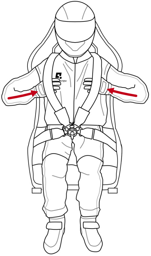
2. All tongues of the seat belt should be fastened to the buckle, as shown in the picture.
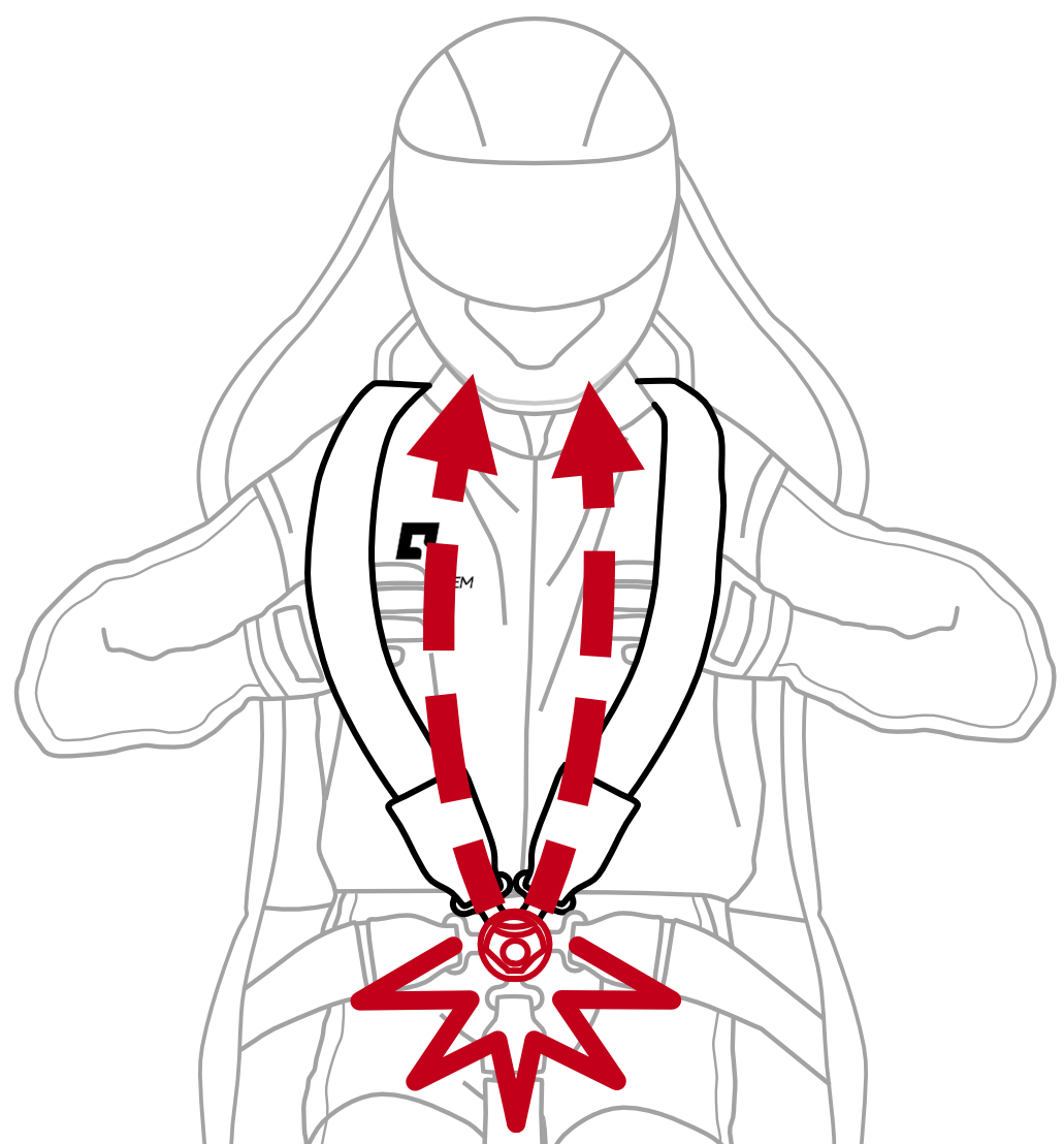
1. Correct seat belt tension can be determined by placing your hands underneath the belts. If your hands can move freely - tighten the belt. If you cannot put your hands under the belt - loosen the belt.
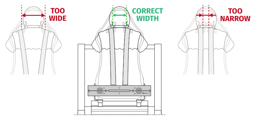
Info
For the most realistic and immersive experience, seat belts should be horizontally positioned with the same width as your neck width. If the belts are positioned too wide or too narrow, pain or scratches in the neck area will occur.
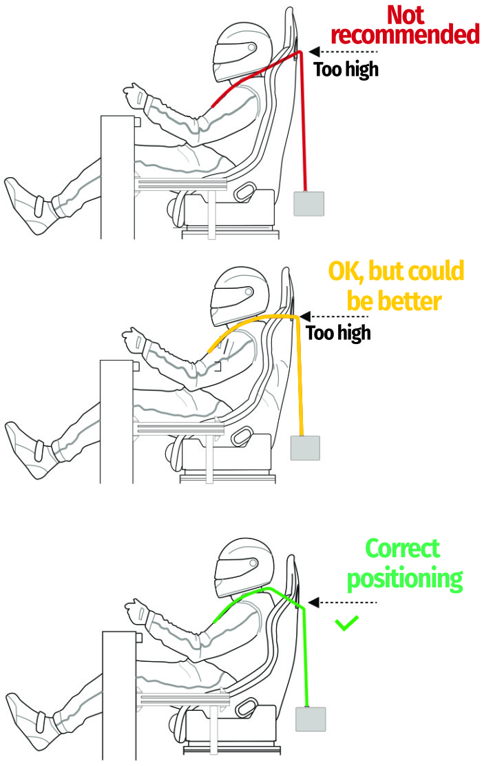
4.8.2 Vehicle vs. flight simulations setup
Info
To have the most immersive experience in vehicle or flight simulations you need a compatible seat with specific seat belt slots height.
In vehicle simulations you should have horizontal pulling force instead of upward or downward pulling force. Seat belt slots should be at the same level as your shoulders.
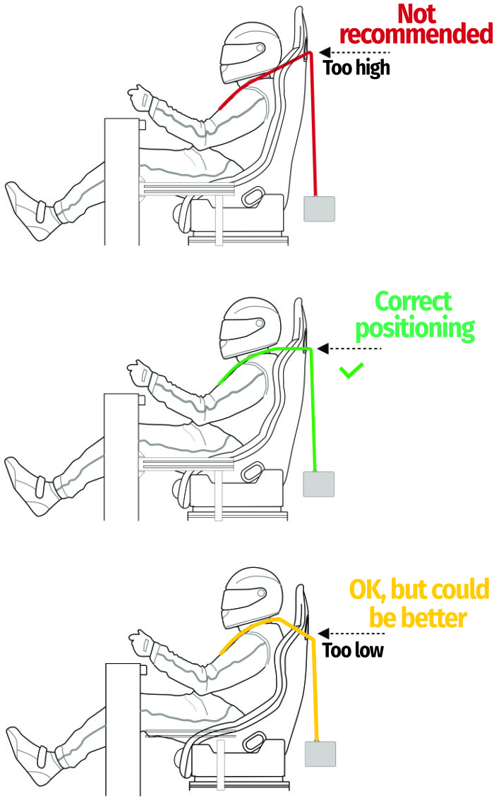
In flight simulations you should have downward pulling force instead of upward or horizontal pulling force. Seat belt slots should be positioned lower than your shoulders.
4.8.3 Attaching tensioner buckles to the harness
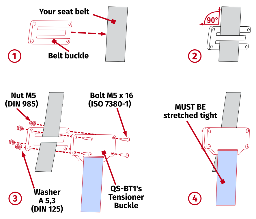
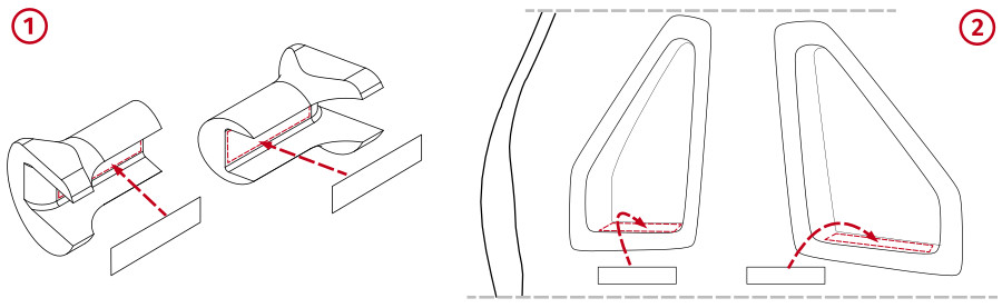
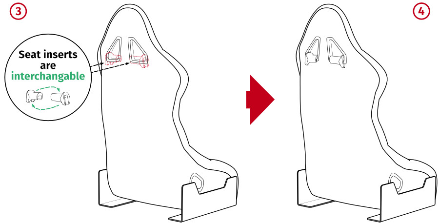
QS-BT1 's Tensioner Buckles should be mounted to your seat belts (harness) using included Belt buckles and fasteners. Use seat inserts for the holes in your racing seat.
Assembly parts included with QS-BT1 :
| No. | Part description | Qty. |
|---|---|---|
| 1 | Belt buckle | 2 |
| 2 | Bolt M5 x 16 (ISO 7380-1) | 8 |
| 3 | Nut M5 (DIN 985) | 8 |
| 4 | Washer A 5,3 (DIN 125) | 8 |
| 5 | Seat inserts (interchangeable) | 2 |
| 6 | Velcro strips | 2 + 2 |
Info
Illustration of a finished belt buckles assembly.
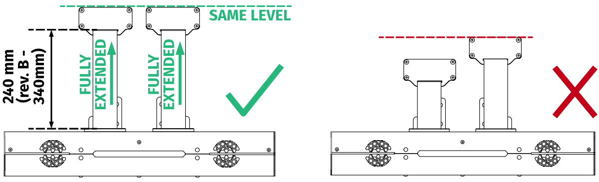
Info
When reinstalling a previously used device, ensure that the belts are correctly extended (unrolled from the inside).
Warning
All operations MUST be performed with the power OFF.
Tip
Order of operations:
- Attach the racing harness to a cockpit and adjust it for the user (section 4.8.1). QS-BT1 must be attached to an already correctly setup racing harness.
- Attach the fully extended tensioner buckles to the harness, leaving a minor slack. It is suggested to clamp the harness with belt buckles without torquing the bolts, then check the setup again.
- While tightening the bolts, keep the belt buckles pulled upward to prevent them from lowering during installation. Refer to the belt tightness illustration for a visual example of the desired result (belt tightness illustration).
- Run your seat belt through the belt buckle and mount it with QS-BT1 's tensioner buckle. Start from screwing in top bolts, then proceed to the ones below. Ensure they are perpendicular to the belt.
Before screwing the bolts down ensure proper tightening of the belts.
QS-BT1 's belts should a minor slack - do not force them tight, since they will be tensioned later by the QS-BT1 after in-game engagement (for more details go to section 6).
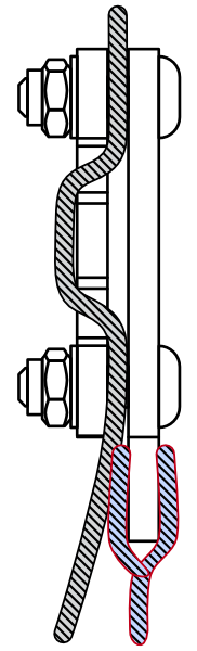
- Refer to the illustration on the right for a correct belt intertwine between belt buckle bars longrightarrow Ensure correct mounting of the tensioner and belt buckles as this may have negative impact on device's performance and user's feeling of immersion. The belt tensioner generates a maximum of 200 N of force on each side. Install adjustable seat belts that can withstand forces generated by the device, preferably with FIA certification.
 InfoRevision A (prototype) and B of the QS-BT1 are using respectively 6 and 5 (instead of 4) assembling bolts and different type of belt buckle (with different assembly hardware):
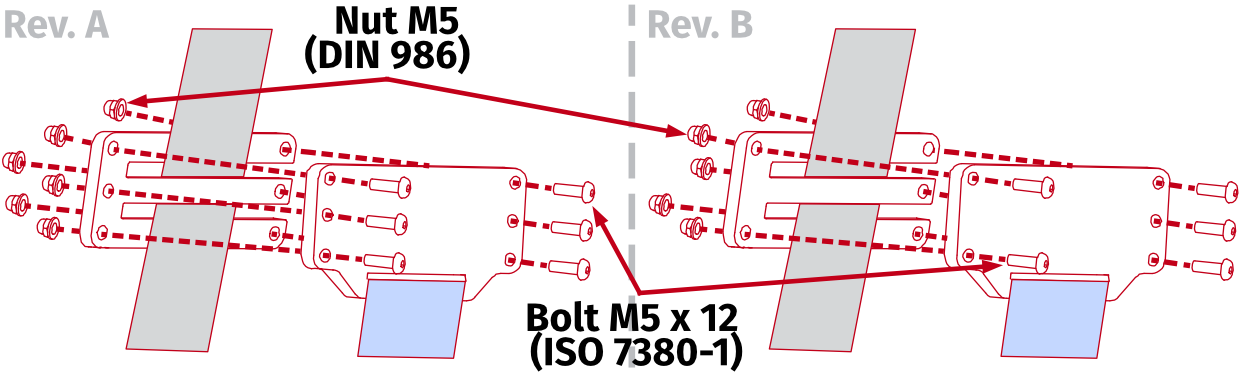
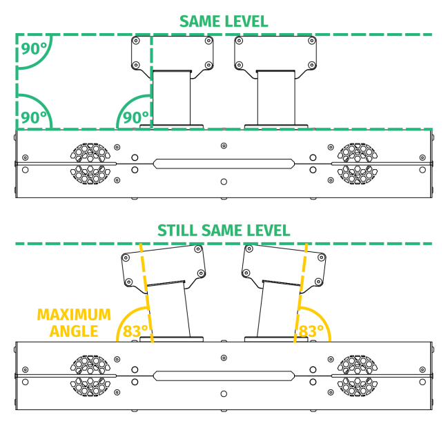
- QS-BT1 's Tensioner Buckles should be mounted on the same level and evenly in relation to each other - parallel to the QS-BT1 's main unit.
- Excess belt should be rolled and attached permanently to rest of the harness. It cannot interfere with platform movement.
- Attach the fully extended tensioner buckles to the harness, leaving a minor slack (without forcing the belts upward). The racing harness should be tight. Heavily sagging QS-BT1 's belts will reduce the feedback on details.
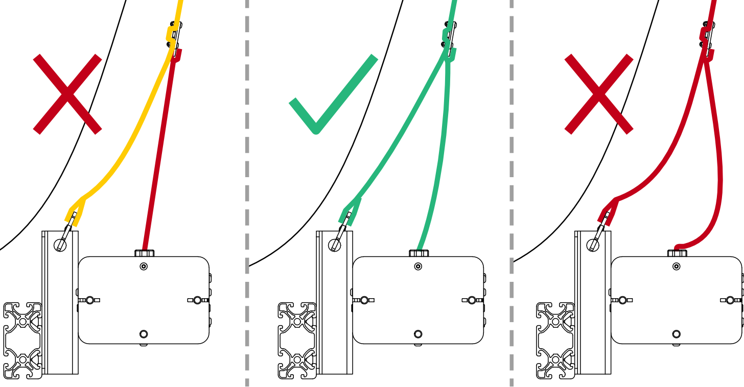
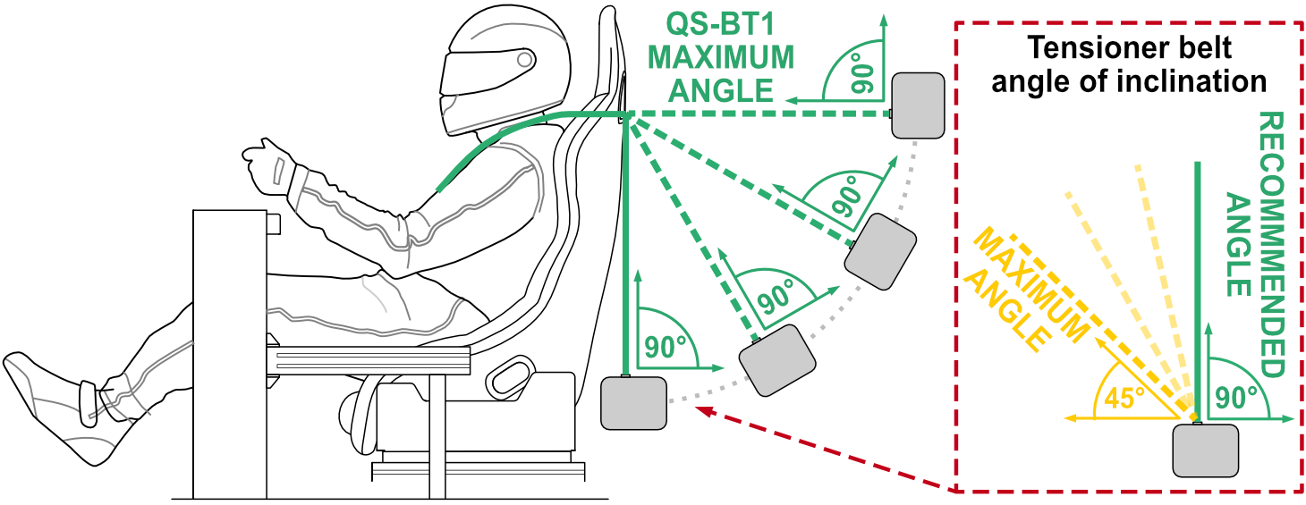
- If necessary, the device can be installed further away. Preferably the assembling method would ensure that the belts are perpendicular to the device. Maximum angle of belt inclination is 45 degrees.
If the belts rub against the housing while in normal operation - the pulling force will significantly drop, reducing the immersion.
 WarningIn case of motion platform implemented cockpits - the QS-BT1 always MUST BE mounted to a position that is moving along with the seat. In order for QS-BT1 to work correctly it is recommended that it always is mounted directly to a cockpit and not separately.
4.8.4 Seat inserts
Info
Seat inserts are provided with the QS-BT1 mainly to reduce friction on the harness. They also guide your belts better, prevent the seat from getting worn down and reduce the sound of harness rubbing against the harness slots.
Info
User may use an alternative solution for smooth harness operation, e.g. aftermarket rollers. However - minimum recommended roller diameter is no less than 35 mm. Small diameter will cause bigger bend angle on the harness and will restrict tensioning force for the user, thus lowering the immersion.
4.9 Cable connections
Warning
Power cords used to power QS-BT1 or other devices MUST NOT run alongside the QS-BT1 's USB cable. They MUST be separated to allow for reliable connection with the PC.
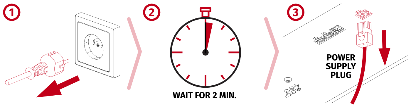
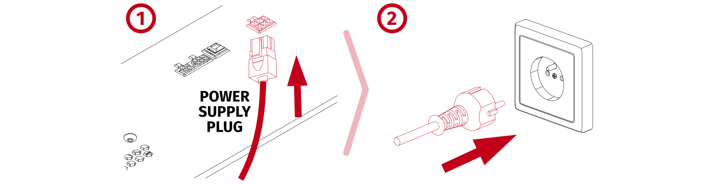
4.9.1 Before connecting Power
Warning
The operation of connecting cables must ALWAYS be carried out with the power switched OFF.
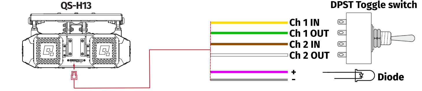
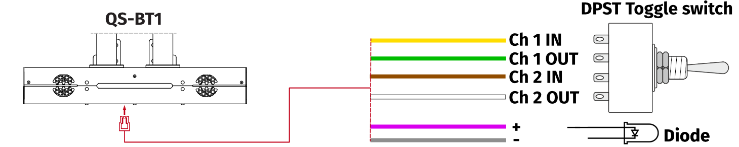
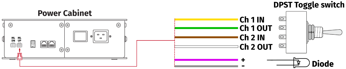
4.9.2 Basic connection diagrams
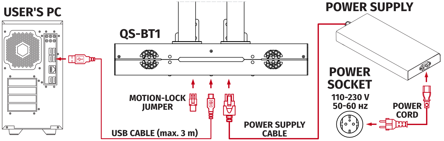

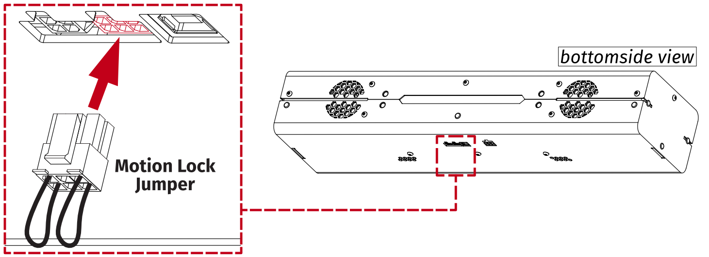
Warning
If QS-BT1 is not included in Motion Lock circuit, then Motion Lock jumper MUST be plugged in, as shown in the illustration below.
Info
- QS-BT1 supports a USB connection via cable with a MAXIMUM length of 3 meters between the device and a PC. Do not use a USB extension cable.
- If necessary, use only high-quality powered USB hubs. For reliable operation, use a short USB cable (less than 1 metre) and connect through a powered hub.
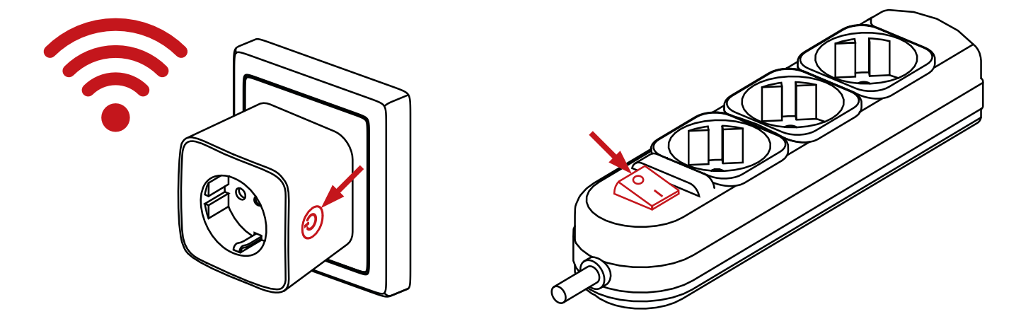
Info
To ensure safe power disconnection from QubicSystem device power supplies, it is recommended to use an external power switch — such as a power strip with a switch or a smart plug (rated for min. 10A).
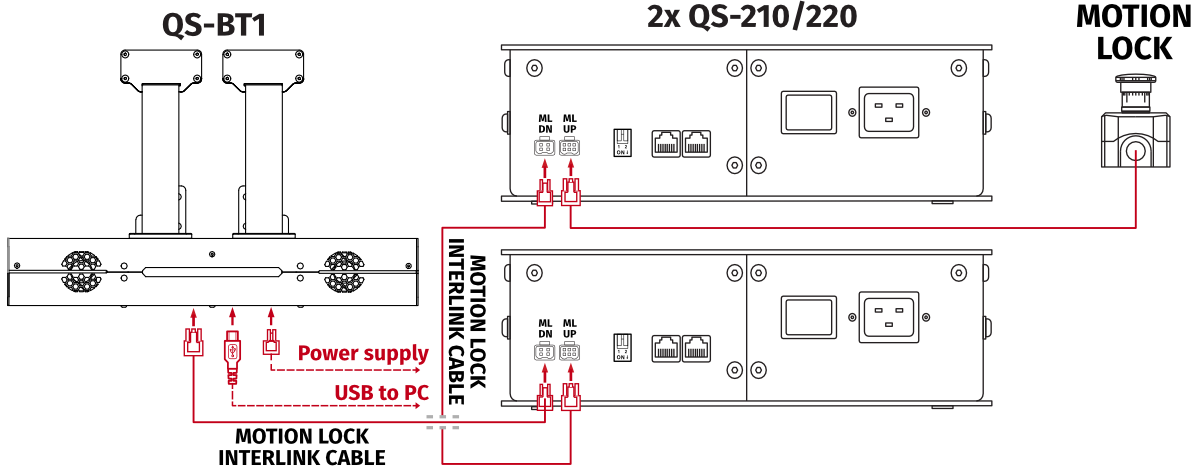
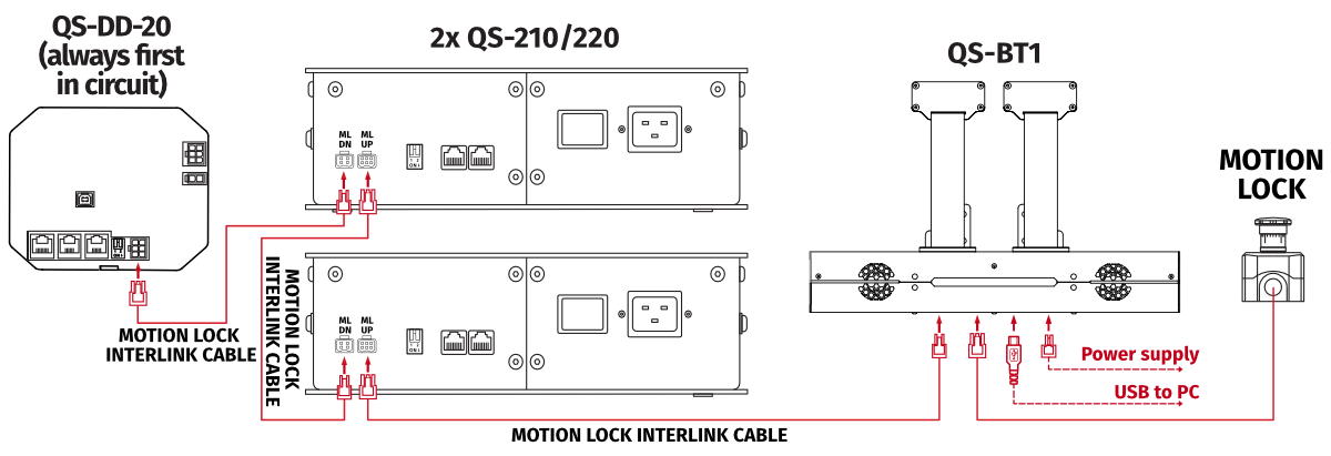
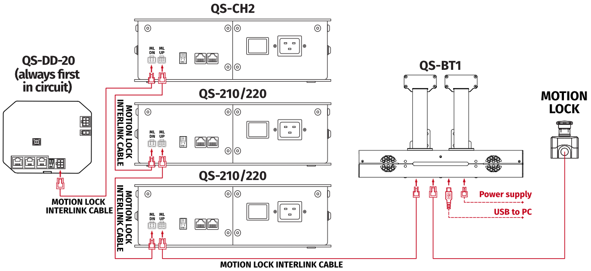
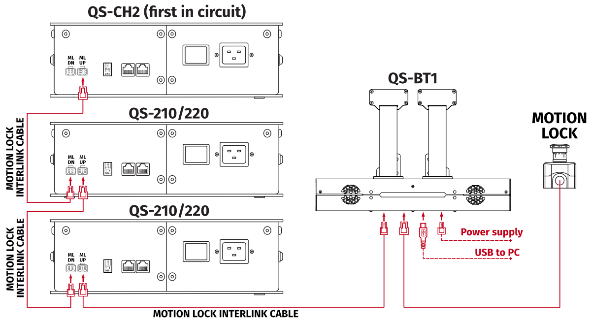
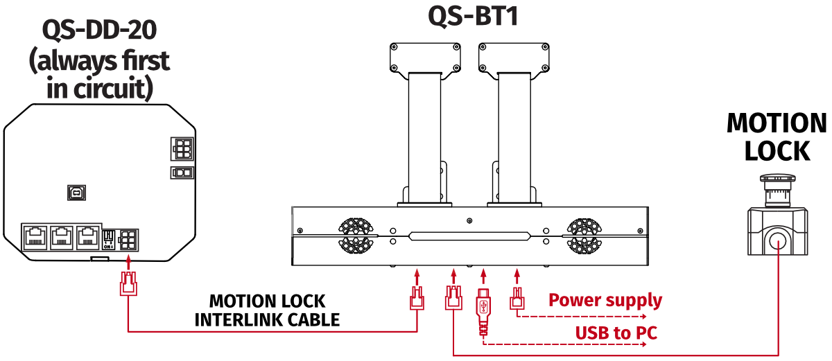
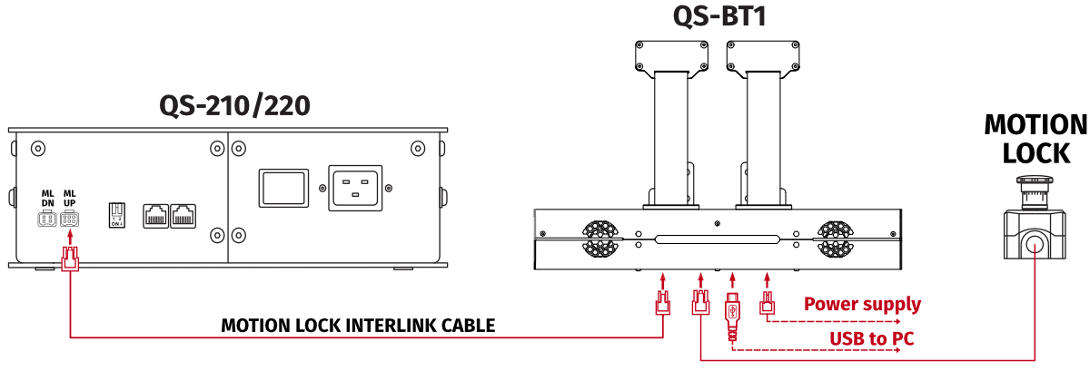
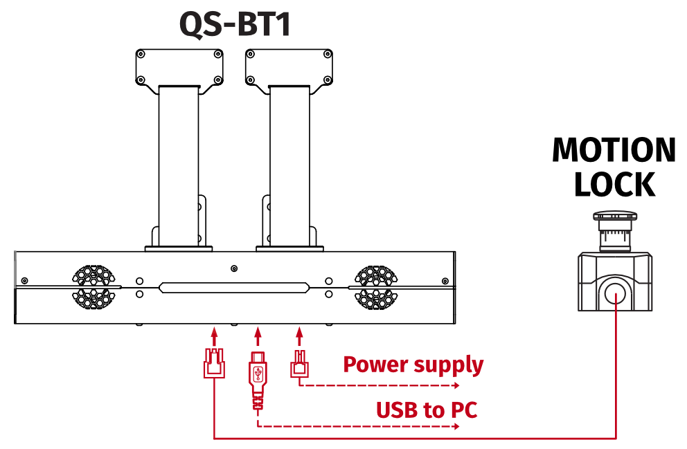
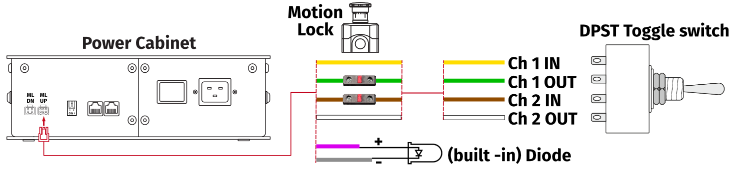
4.9.3 Motion Lock connection diagrams
It is recommended that you install a Motion Lock button within arm's reach of the user. It is possible to run QS-BT1 device individually with a dedicated Motion Lock button. It is not included and can be purchased separately as an accessory from our retailers.Warning
- All Motion Lock connections must be performed with power OFF.
- Motion Lock interlink cables have different ML/UP (6 pin) and ML/DN (4 pin) plugs on each side.
- Motion Lock is not a standalone device - QS-BT1 must be plugged in to power and via USB to PC.
Info
We recommend including QS-BT1 in the Motion Lock circuit, if you are running other QS-series devices. Refer to diagrams below.

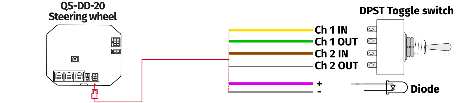
4.9.4 Implementing non-factory Motion lock switch
For non-factory Motion Lock plug setup, you must assemble plug and connectors as shown below: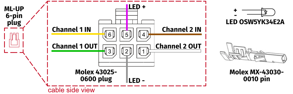
4.10 Post-assembly checklist
After successfully connecting the QS-BT1 to the power, PC and installation to the platform - check if everything is ready to operate: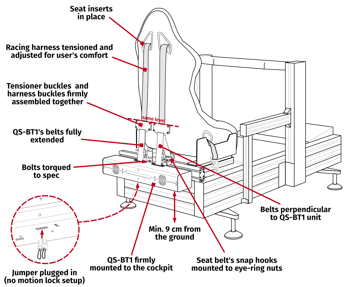
5 Software
This section refers to the QubicManager, which is the default Qubic Systems software. If you already own another Qubic System device, the QS-BT1 will be automatically added to your device list in the5.1 QS-BT1 software compatibility
Choose the software based on your primary motion platform family.| Device | Qubic Manager | ForceSeatPM | Next Level Racing® Platform Manager |
|---|---|---|---|
| QS-BT1 | ✓ | ✓ | ✓ |
| QS-H13 | ✓ | ✓ | x |
| QS-210 | ✓ | ✓ | x |
| QS-220 | ✓ | ✓ | x |
| QS-CH2 | ✓ | ✓ | x |
| QS-S25 | ✓ | ✓ | x |
| QS-S35 | ✓ | ✓ | x |
| QS-V20 | ✓ | ✓ | x |
| PS-6TM-XXX | ✓ | ✓ | x |
| PS-6TL-XXX | ✓ | ✓ | x |
| PS-3TM-XXX | ✓ | ✓ | x |
| PS-2RM-XXX | ✓ | ✓ | x |
| Next Level Racing® Motion V3 | ✓ | ✓ | ✓ |
| Next Level Racing® Motion Plus | ✓ | ✓ | ✓ |
| Next Level Racing® Traction Plus | ✓ | ✓ | ✓ |
| No motion platform | ✓ | ✓ | ✓ |
| 3rd party motion platform** | ✓ | ✓ | ✓ |
Info
If you have previously installed the software, ensure that it is up to date before running the QS-BT1 .
5.2 Download and installation
Info
If you already have software installed, no changes are necessary - device will be automatically added to device list, and all steps from this section should be skipped.
Software installation procedure:
- Connect the devices according to the interconnection diagram without connecting the power supply unit to the power socket - see section Cable connections (if it is equipped with a power switch, keep it in OFF position).
- Download QubicManager from QubicSystem.com/Download
- Enter the serial number located on the identification label.
- Proceed with the installation steps and launch the application.
- Turn on the device by connecting power supply unit to the power socket (if it is equipped with a power switch, turn it ON).
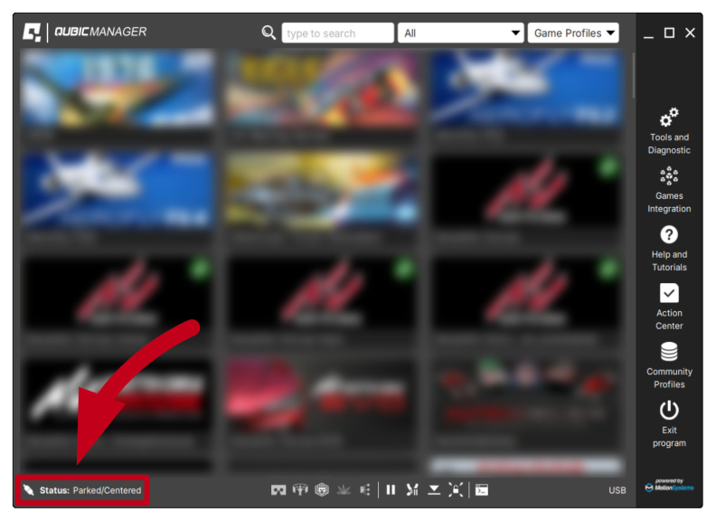
- If QubicManager has recognized the QS-BT1 correctly, the status of the device will change to Connected. Device status is visible in the lower left corner.
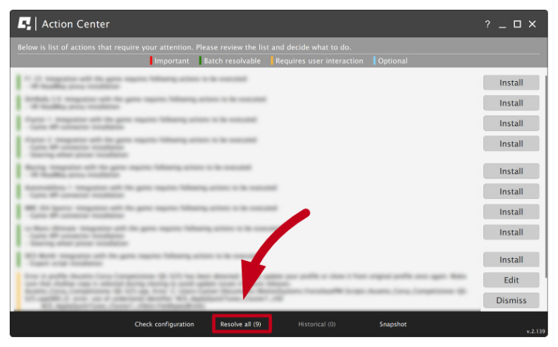
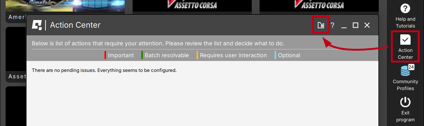
- Check the Action Center on the right side panel for a list of actions that require attention. It is possible to solve them one by one or by pressing the Resolve All button. Firmware updates may require additional confirmation in the dialogue box.
5.3 Adjustments
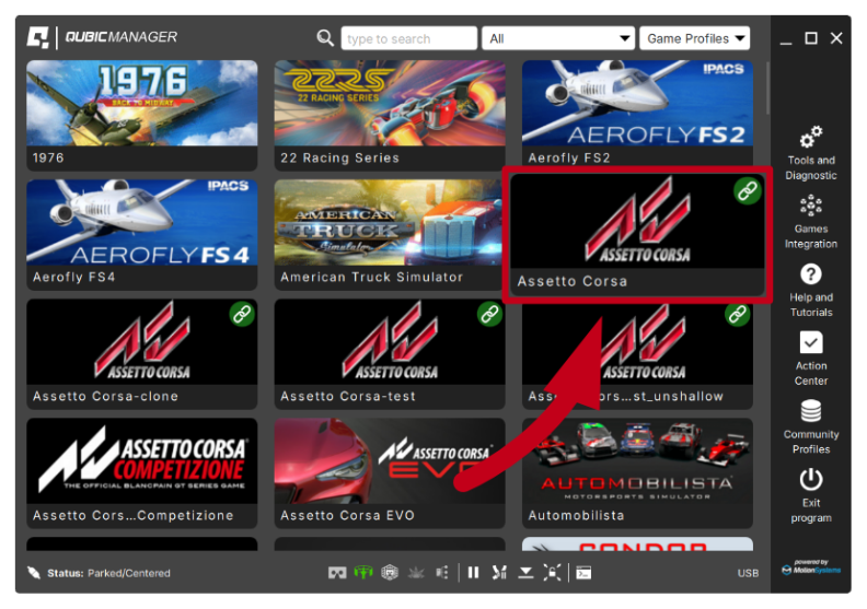
- Select the profile in the Qubic Manager main application window:
InfoDefault profiles are integrated with the software and do not require additional installation. List of supported games is available at: QubicSystem.com/Supported-games.
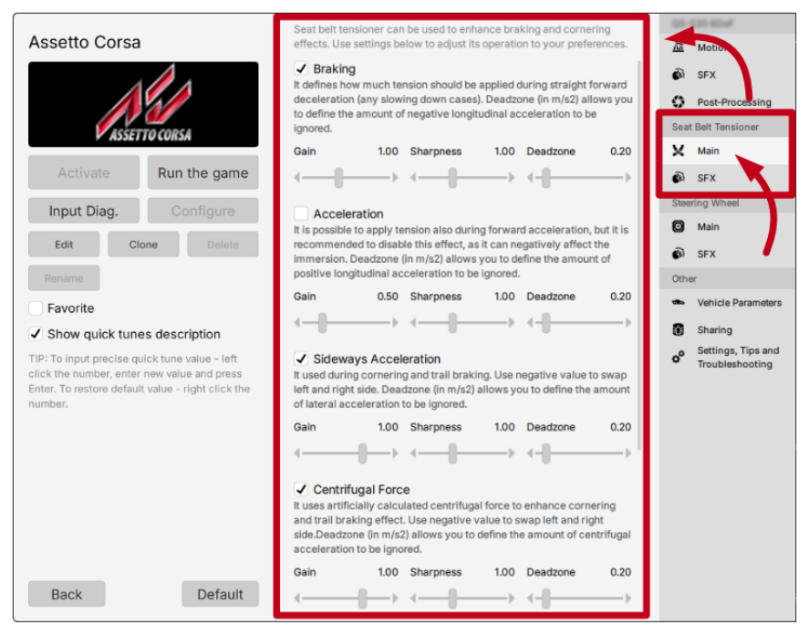
- In the profile window, in the tab "Seat Belt Tensioner" select "Main" or "SFX" and then adjust the settings to your own preferences using sliders in the profile window. Changes can be made "on the fly" without quitting or restarting the simulation application.
6 Operation
Info
For connecting and setting up the QS-BT1 , see section Cable connections at page .
- After turning on the QS-BT1 , red light scanning effect at the led bar begins. The device is in standby mode.

- Launch QubicManager software (QS devices need QubicManager software to operate in background). For details refer to section 5 at page .
- Activate a correct profile in QubicManager main application window. (if game is launched without activating a profile - software will activate a default profile automatically).
InfoDefault profiles are integrated with the software and do not require additional installation. List of supported games is available at: QubicSystem.com/Supported-games.
- You may check the status of the device in bottom left corner - it should say "Connected".
- No calibration of the device is needed.
- The QS-BT1 will start tensioning the belts after in-game race or flying session will begin:
- In a racing simulation the QS-BT1 will tension the belts (depending on a game) after firing the engine, first braking or a downshift action.
- In a flight simulation the QS-BT1 will tension the belt (depending on a game) after sudden braking on a landing strip or a sudden control stick movement while in the air.
- Anytime you pause or exit the game the QS-BT1 will release the tension of the belts.
- After you resume the game the QS-BT1 will tension the belts again after any action from point 6 (a) or 6 (b) will occur.
7 Troubleshooting
Warning
DO NOT attempt to do any repairs by yourself. It is dangerous and will result in loss of warranty! All repairs should be consulted with technical support and performed by a qualified technician.
- Check the Action Center in QubicManager.
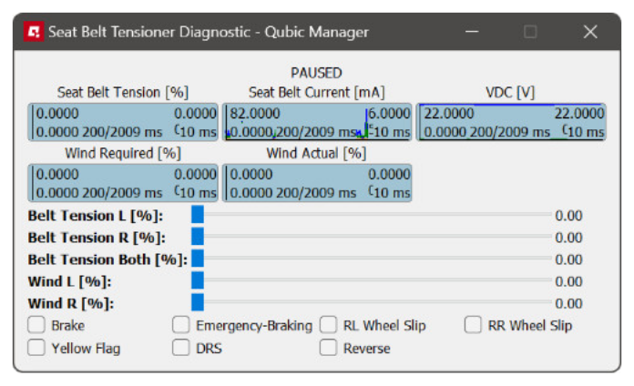
- Open the diagnostic window to check if the device is responsive.
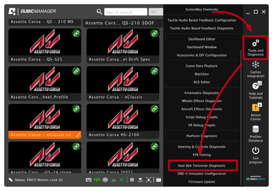
- Select Tools and Diagnostic → Seat Belt Tensioner Diagnostic
- Diagnostic window allows pulling belts by using the sliders. It also displays the input data signal from the application.
- Select Tools and Diagnostic → Seat Belt Tensioner Diagnostic
- Check all cable connections of the device. Refer to section Cable connections.
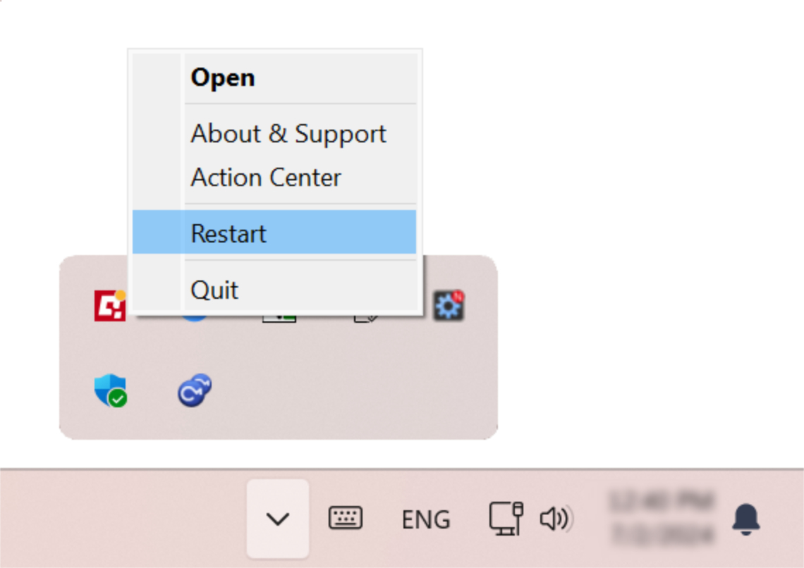
- Restart QubicManager application by right-clicking on the application icon in the system tray and selecting Restart
- Try different USB ports in your PC.
- If a problem occurs abruptly, it could be caused by thermal protection. Turn off QS-BT1 , disconnect it from power outlets and wait at least 15 minutes to let it cool down.
- In case of any unclear electrical issues or strange behavior, contact technical support.
- If the device suffers from abnormal work conditions, please immediately contact the distributor/reseller for technical support.
Info
If none of the diagnostic advice listed above works, create a snapshot. It compiles all the necessary details for technical support to resolve the issue.
7.1 Common problems with solutions
- Problem: Belts do not release/belt release is weak.
First verify if user's profile is causing the no-release problem - constant flow of game inputs may be making the belt tension without stop. To verify that:
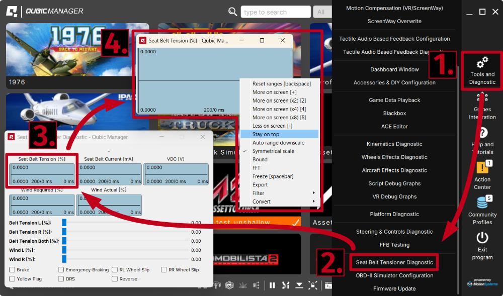
- Go to QubicManager → "Tools and Diagnostics" (1) → "Seat Belt Tensioner Diagnostic" (2).
- Open and enlarge the "Seat Belt Tension [%]" (3) graph.
- Right-click on it → "Stay on top" (4).
- Check if lines ever go down to 0 during normal game session.
Solution #2: If the lines go down but belts do not release - harness/belt's friction is too high. Since the force of the belt tension is regulated by the motor, but the release of the belt is not, user must ensure the least possible friction on the harness and built-in belts. QS-BT1 must be mounted according to the manual (section Correct belt angles, p. ). Low friction inserts must be installed (or possibly aftermarket roller setup - more info in section 4.8.4, p. ).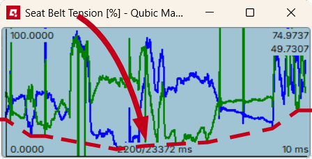
- Problem: Belts are not working symmetrically/one belt is weaker.
First verify that belts have symmetrical pulling force.
While the QS-BT1 is ON and the user is sitting in the rig with belts fastened:
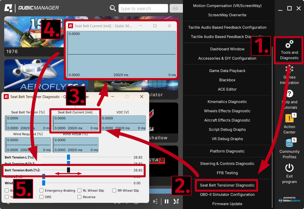
- Go to QubicManager → "Tools and Diagnostics" (1) → "Seat Belt Tensioner Diagnostic" (2).
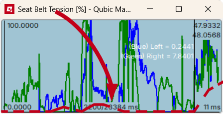
- Open and enlarge (double-click) the "Seat Belt Current [mA]" graph (3).
- While observing the graph (4), move the slider "Belt Tension Both [%]" (5) slowly to the right and back to the left. Focus and feel whether the right and left belt pulls with the same force (small oscillations on graph are normal due to uneven mouse movement).
- there is too much friction on one of the sides
- the harness is installed incorrectly (unevenly, bolts not torqued down)
- the harness is coming loose on the chest adjusters
- QS-BT1 is not installed in vertical center axis of the seat which causes the belts to slip to the side and rub against the seat harness slot
Solution #2: If two lines clearly do not match each other - report the problem to Technical support via application form on the Motion Systems website, including a snapshot file (section 7.3). Solution #3: If there is no pulling force on one of the belts and the device is emitting unusual noises - report the problem to Technical support via application form on the Motion Systems website, including a video of a working QS-BT1 .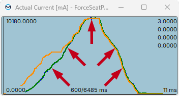
- Problem: QS-BT1 does not calibrate at start-up.
Solution: QS-BT1 does not have a calibration procedure. Once the belts are fully extended and the device is connected according to the diagrams - it is ready to operate. Once in the game/simulation - the first input signal sent to the QS-BT1 will start tensioning the belts (for details on operation of the device, go to section 6, p. ).
- Problem: QS-BT1 keeps disconnecting/does not connect at all.
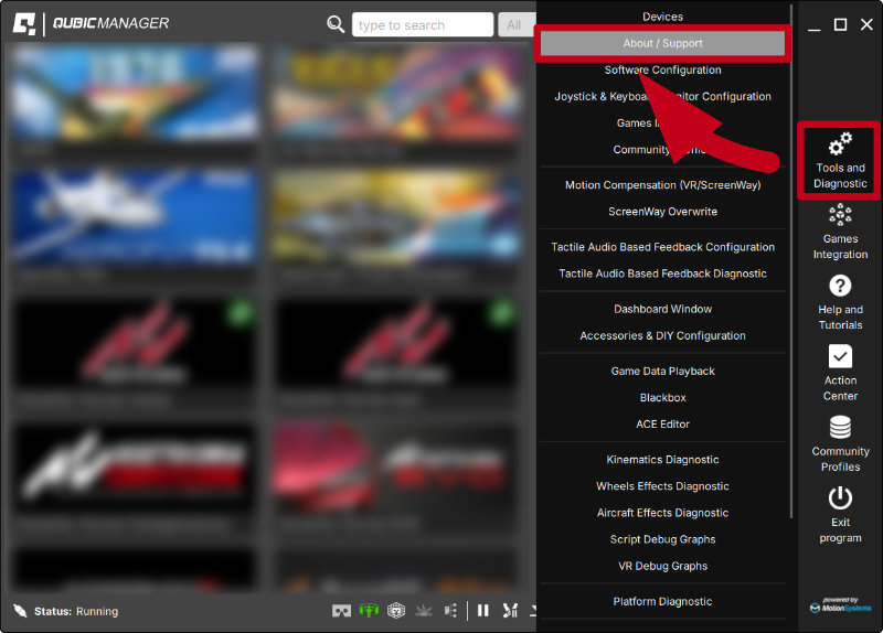
Solution #1: Make sure QubicManager software is up to date. Go to QubicManager → "Tools and Diagnostic" (1) → "About / Support" (2) → check the software version (3)
 Compare it to newest software version listed on Qubic System website: QubicSystem.com/qschangelog → "Software" → "Changelog".
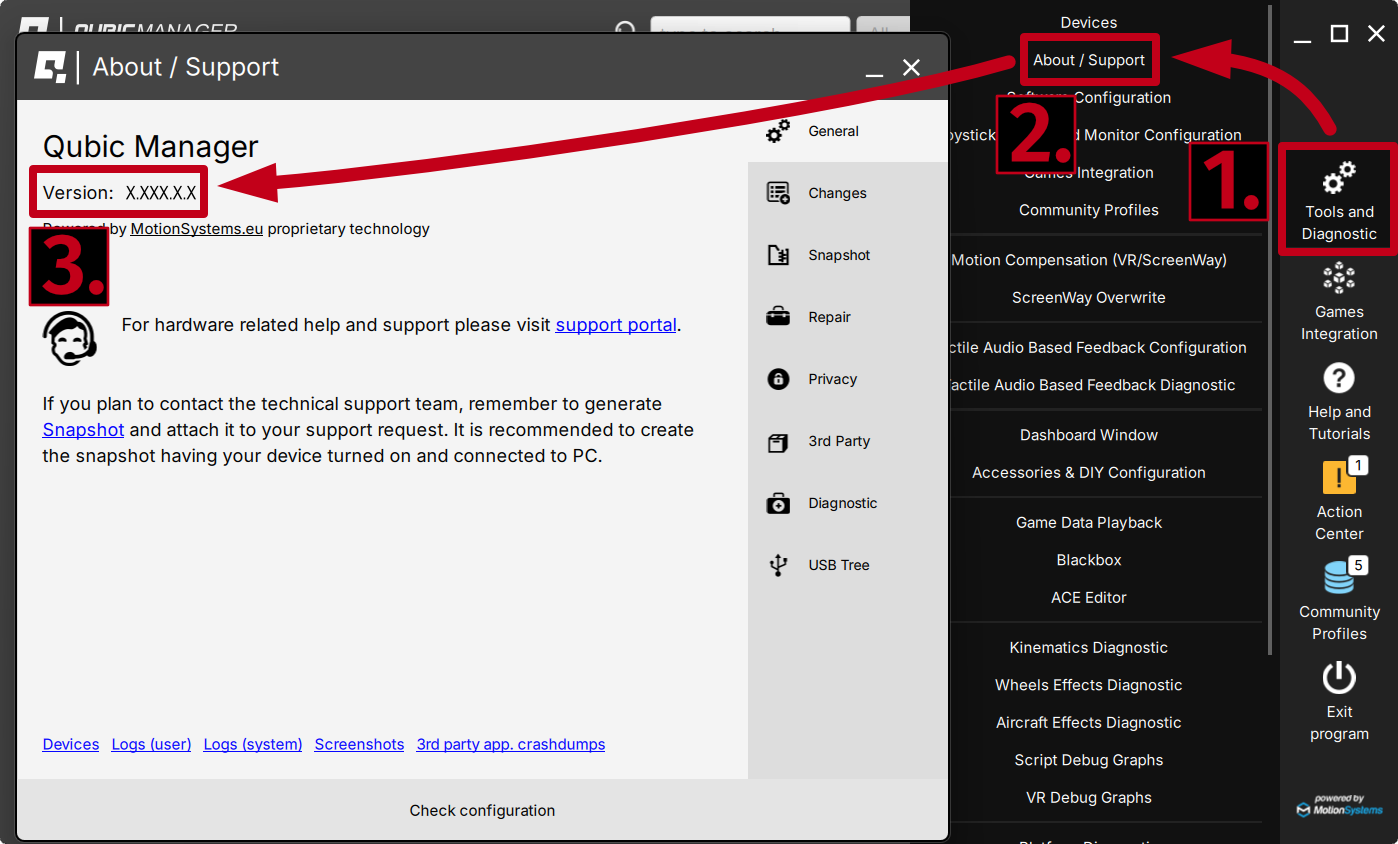 Solution #2: Check Action Center in QubicManager for pending issues. Click "Resolve all" button if there are any issues or resolve them one by one.
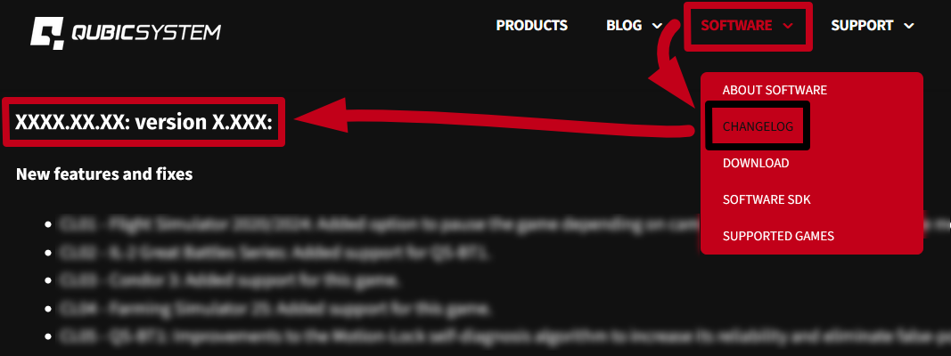 Solution #3: Pass over the USB Hub - connect the device directly to the PC. Solution #4: Plug the QS-BT1 to a different USB Port. Solution #5: Replace the original USB cord (Type B USB plug).
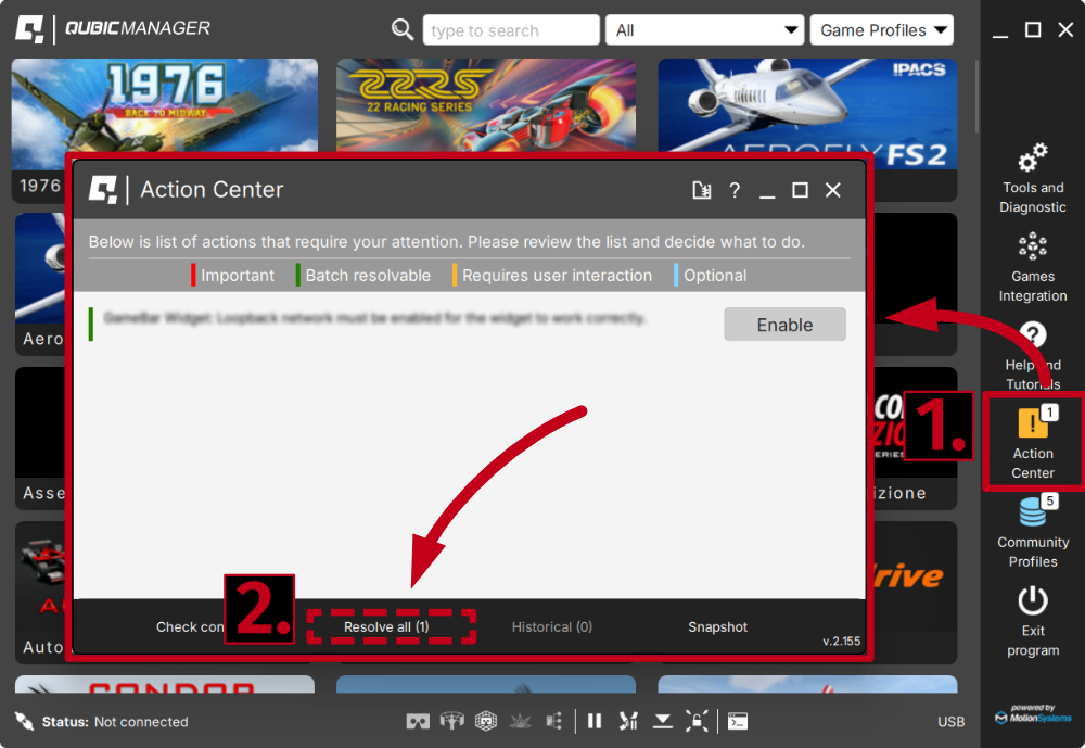 Solution #6: Separate power cords from QS-BT1 's USB cable so that they do not run alongside each other.
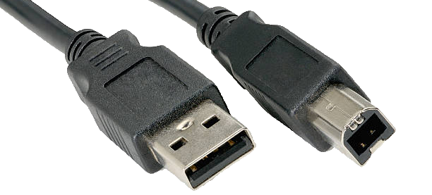 If none of the solutions above work - report the problem to Technical support via application form on the Motion Systems website and include a snapshot file (section 7.3).
To avoid any potential problems or damage to equipment NEVER disconnect or connect the Power Supply plug to the QS-BT1 with Power ON. For details - go to section 4.9.1.
- Problem: QubicManager software crashes on launch with an OpenGL error.
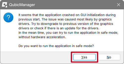
Solution short-term: To open the app, click OK on all the operating system errors. Restart the QubicManager software and you will be presented with a window:
Click "YES" if you want run the application in Safe Mode (it will run a little slower). Solution long-term #1: In order to overwrite the OpenGL rendering backend permanently, type in troubleshooting in Windows search bar. Select Qubic System Troubleshooting Assistant.

In the prompt window, type 6 on your keyboard and click Enter. Restart the QubicManager application.Solution long-term #2: This issue is caused by graphics drivers. Try to downgrade to a previous version of graphics drivers or check for updates.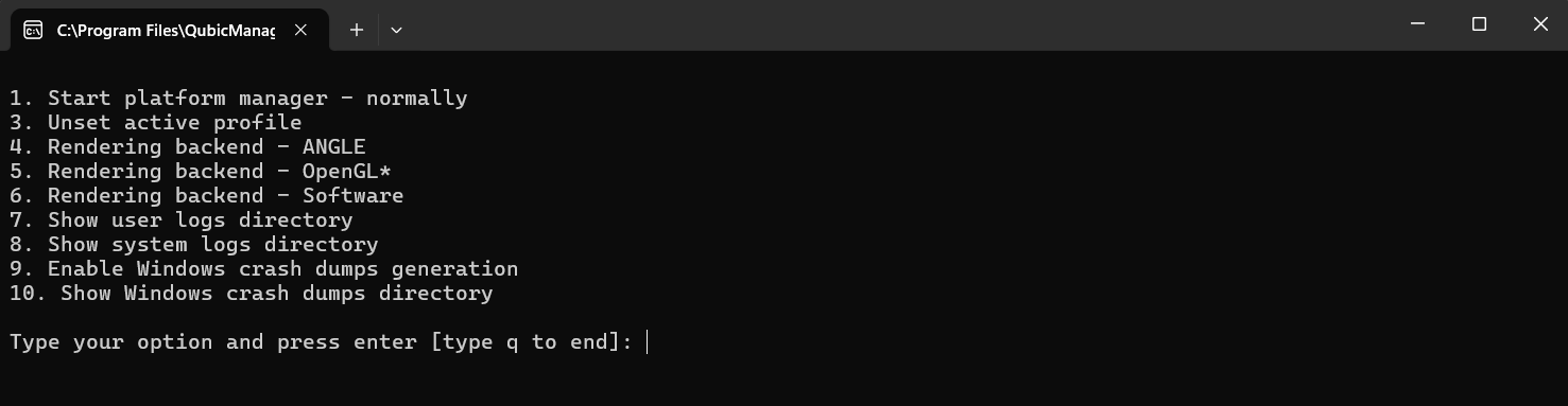
- Problem: QS-BT1 does not work when the car hits rumble strips/curbs.
Solution #1: To verify that QS-BT1 is working correctly try a different game/simulation. It is possible that different games/simulations will provide QS-BT1 with different data.
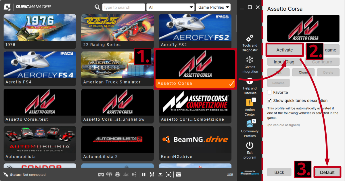
Solution #2: Activate a default game profile (2) (always the first one in a given game title list (1)) and bring all the sliders to a default setting by clicking "Default" button (3) and then "Yes to all".
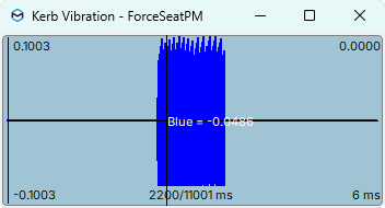
Solution #3: Increase Rumble strips/Road harshness slider value.Tip: If QS-BT1 is working correctly and only the rumble strips/curbs are not present - most likely it is the lack of input from the game. To verify what input signal is being sent to any QS device - go to your currently activated game profile → "Input diag." and watch the graphs during typical game session. Double click to open in a new window -> right click on a graph -> Stay on top. Illustration of a "Kerb Vibration" graph after hitting a rumble strip: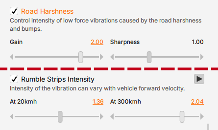
7.2 QubicManager device statuses
- no device is detected. If status appears while device is connected - check if the Power Supply Unit is working correctly. Also USB connection could be at fault. Check USB connection for loose connections, try different USB ports, bypass any USB hubs, swap USB cable for a different one. Lastly - firmware update could have failed (requires firmware recovery). - the device is operational/in simulation/receives input signal.
 - the device is paused (Pause button at the bottom of the QubicManager window).
 - Motion Lock system has been triggered. Unpress the Motion lock button, check the Motion Lock button cable/connection. In a setup with no Motion Lock button - check the Motion Lock jumper.
 - there is an issue with the connection or power - check the working status in Tools and diagnostic → Devices.
 Info
Info- ALL diagnostics and cable connection inspections MUST be performed with the device powered OFF.
- If any of error statuses persist after performing the troubleshooting steps - please contact technical support.
7.3 Creating a snapshot
A snapshot is the easiest and fastest way to diagnose a problem. If you send in the zip file generated in the snapshot menu along with a description of the problem, technical support receives all the necessary information about the product and its configuration. It can be then analyzed to provide the best solution.Info
The QS-BT1 and all interconnected Power Cabinets MUST BE be powered up when creating the snapshot.
- Open the main window of the QubicManager application.
- Go to Tools and Diagnostic → About / Support.
- Open the Snapshot window:
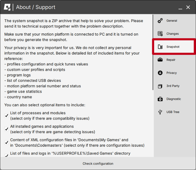
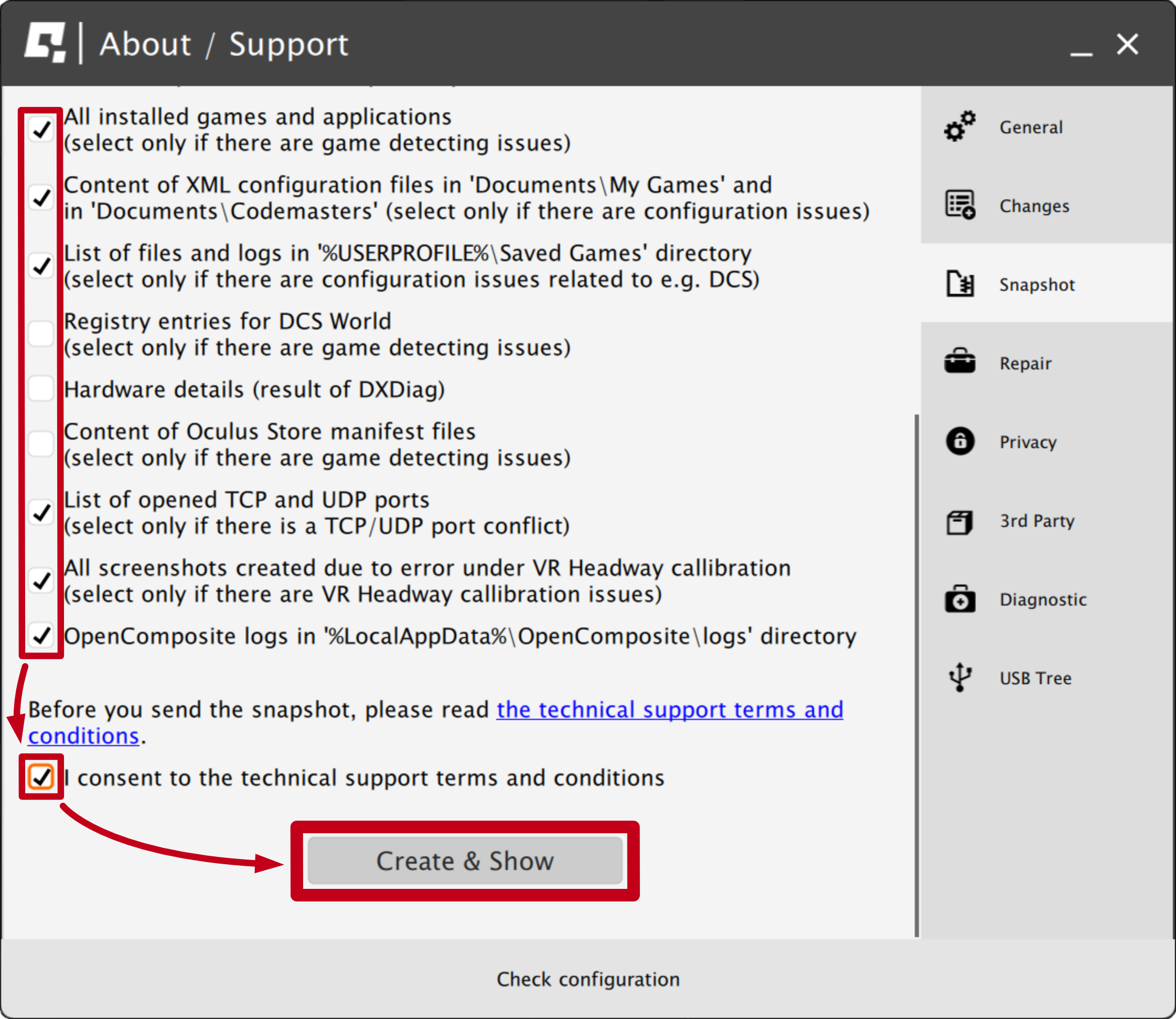
- Select data that will be included in the snapshot.
- Scroll down, consent to the technical support terms and conditions and select Create & Show:
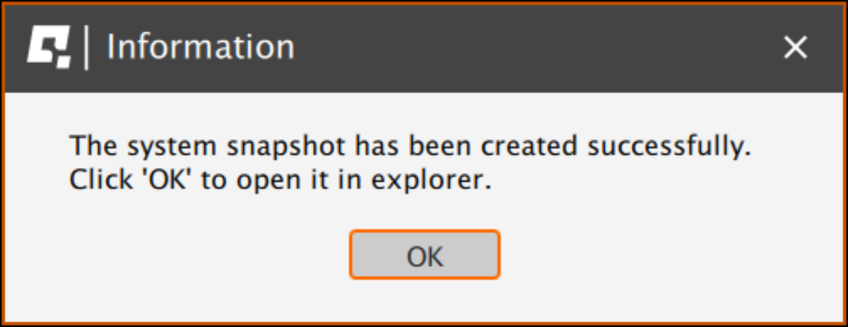
- The snapshot has been created, click the OK button - the folder with the snapshot ZIP file will open.
- Attach the snapshot ZIP file to your support request.
7.4 Discord channel
We strongly recommend joining our discord channel, where our growing community is sharing amazing tips and ideas of how to set up, use and tune the Qubic System products. You can also send questions for technical support or get answers directly from the community.
Join our discord channel by following the invitation link:

8 Conformity information

The QS-BT1 meets the requirements of CE marking and relevant regulations of the EMC Directive 2014/30/EU.
9 Environmental Impact and Disposal

DO NOT dispose of this product with standard household waste but drop it off at a collection point for the disposal of Waste Electrical and Electronic Equipment for recycling.
- Metal parts should be scrapped.
- Electric and electronic components should be disposed of in the specialized disposal center.
- Other materials should be sorted and disposed of accordingly to the local law and regulations.
10 Liability Disclaimer
If permitted under applicable law, Motion Systems and its subsidiaries disclaim all liability for any damages caused by one or more of the following:- The product has been modified, opened, or altered.
- Failure to comply with assembly instructions.
- Inappropriate or abusive use, negligence, an accident (an impact - for example).
- Normal wear.
Info
If permitted under applicable law, Motion Systems and its subsidiaries disclaim all liability for any damages unrelated to the material or manufacturing defect with respect to the product (including, but not limited to, any damages caused directly or indirectly by any software, or by combining the QS-BT1 with any unsuitable element or other elements not supplied or not approved by Motion Systems for this product).
11 Warranty
Motion Systems warrants to the consumer that this product shall be free from defects in materials and workmanship, for a warranty period which corresponds to the time limit to bring an action for concerning this product. For commercial customers there is a one (1) year limited warranty, starting on the original date of purchase. For non-commercial customers there are two (2) years warranty, starting on the original date of purchase. Within the warranty period, the product will be repaired or replaced free of charge, excluding shipping charges. This warranty shall not apply:- If the product has been modified, opened, altered, or has suffered damage as a result of inappropriate or abusive use, negligence, an accident, normal wear, or any other cause unrelated to a material or manufacturing defect (including, but not limited to, combining the QS-BT1 with any unsuitable element, including in particular power supplies, chargers, or any other elements not supplied or approved by Motion Systems for this product).
- In the event of failure to comply with the instructions provided by technical support.
- To software (said software being subject to a specific warranty).
- To accessories (cables, cases, for example).
- If the product was sold at public auction or if the product has suffered damage as a result of force majeure: flood, fire, earthquake, storm.
12 Copyright
Qubic System is a trademark of Motion Systems. All rights reserved. All the contents in this user manual are the intellectual property of Motion Systems. No part of this manual, including the products and software described in it, shall be modified or translated into any language without the prior written permission of Motion Systems. Specifications and information in this manual are subject to change at any time without obligation to notify any person of such revision or changes. Illustrations are not binding.Info
Trademark Notice - All brand names, icons, and trademarks that appeared in this manual are the sole property of their respective holders.
13 Manufacturer information
Qubic System is a brand
that belongs to Motion Systems
HQ address:
Miedziana 7 Street
55-003 Nadolice Wielkie
Poland
that belongs to Motion Systems
HQ address:
Miedziana 7 Street
55-003 Nadolice Wielkie
Poland


Info
In support queries please contact your reseller.